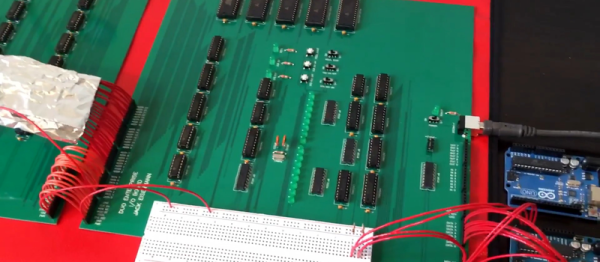
[Jack Eisenmann] is no stranger to building impressive DIY CPU’s on vast stretches of breadboard. This time [Jack] has done away with the seventeen breadboards he used in his last 8-bit computer and instead has gone a step further and designed a set of generously utilised PCB’s for the CPU. The result is the DUO Enterprise.
The CPU design is based around an 8-bit data bus and a 24-bit address bus. As usual, a minimal yet carefully chosen instruction set allows [Jack] to do all the heavy lifting in software as part of the compiler and operating system he is working on. There is no sign of a display yet, instead the computer communicates via a dumb terminal. We love the aluminum foil for shielding! Check out the video, below, to see what we mean.
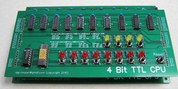
Over the years, we have seen many of [Jack]’s other CPU builds featured on Hackaday. One of his first designs was a 4-bit CPU that could play many games on a LED matrix.Later he did a much more impressive 8-bit CPU along with analog video output and an OS ofcourse. It could even play pong. He even built a Single Instruction Set Computer (SISC).
His final goal with DUO Enterprise is to allow anyone to utilise its computing power by submitting programs and calculations. Heads up [Jack], our neural net needs training soon.