Building A Classic Coin-op Game In An FPGA

This game of Bomb Jack is the same as the original arcade version. The difference is that this hardware was built in an FPGA using schematics found on the Internet.

We’re a little shocked by the complexity of such a project. We’ve been impressed before by the use of FPGAs to implement classic CRT vector graphics. But that project used a library that had already implemented the original game. For this effort, [Alex] wanted to find a game that hadn’t ever been translated to an FPGA, and used stock parts. Bomb Jack is a 1984 platformer which ran on a Z80 processor, AY-3-8192 sound generators, and common TTL logic chips. This meant he didn’t have to write the cores himself, but rather use already existing versions of the chips and code together the hardware.

You can read about his experience at the page linked at the top, or just jump after the break to see video of the final project. You can see the monitor is on its side, and the game sounds great and runs flawlessly.

Continue reading “Building A Classic Coin-op Game In An FPGA”

Can A Robot Be A Safe And Cost-effective Alternative To Guide Dogs?

[Tom Ladyman] is making the case that a robot can take the place of a guide dog. According to his presentation, guide dogs cost about £45,000 (around $70k) to train and their working life is only about six years. On the other hand, he believes that this robot can be put into service for about £1,000 (around $1500). The target group for the robots is blind and visually impaired people. This makes since, because the robot lacks a dog’s ability to assist in other ways (locating and returning items to their companion, etc.). The main need here is independent travel.

He starts with the base of an electric wheelchair — a time-tested and economy-of-scale platform. The robot navigates based on images from four downward facing cameras mounted on the pole seen above. The X on the top of the pole allows for a much wider range of sight. The robot identifies its companion via a tag on their shoe, but it’s got another trick up its sleeve. The cameras feed to a set of four BeagleBoards which work together to process them into a 3D map at about 12 FPS, allowing for obstacle avoidance.

Check out the video after the break for a bit more information. The 3D guidance system is also explained in detail at the link above.

Continue reading “Can A Robot Be A Safe And Cost-effective Alternative To Guide Dogs?”

Alarm System Makes Sure Your Moving Truck Doesn’t Get Raided

When you move you generally load up everything you own into one truck. If your entire life is ever going to get ripped off, this is probably when it’s going to happen. To guard against the threat [Tim Flint] built his own alarm for a moving truck. If someone opens the door on the truck it’ll alert him via text message. Hopefully he’s got an annoying notification sound that will wake him up in time to catch them red-handed.

The setup is simple and shouldn’t distract you too much from your packing and loading. [Tim] connected a proximity sensor to an Arduino board which has its own WiFi module. The entire thing is housed in the black project box seen above and the proximity sensor is pointed at the moving truck door. When the door is opened the Arduino pushes an alert to Twilio which is configured to send him text messages.

The alarm system doesn’t protect from someone stealing the entire truck… that kind of system is an entirely different project.

Tank Router Defends Your Pets?

The guys over at Section9 Hackerspace in Springfield, Missouri just finished building this treaded robot. Despite the juxtaposition of the cat, it really doesn’t defend anything. The project is a reconnaissance robot controlled over the network with video feedback.

The team started off with some lofty goals. They wanted to the robot to be able to climb stairs and to feature a detachable flying portion in order to get a better look at hard to reach places. Cost and complexity are cited as the reasons they ditched the idea of the flyer. The rest of the features came out much as planned. The motor controller for the treads is connected to an Arduino. This uses an Ethernet shield to connect to the WRT54G router which is also coming along for the ride. This seems a bit over-powered but it makes it easy to connect the webcam on the front (also via Ethernet).

On the software side they wrote an Android app. It controls the movement of the robot, as well as that of the camera. Of course you need to see where you’re going so they went the extra mile to include video from the webcam. Check out their show-and-tell video after the break.

Continue reading “Tank Router Defends Your Pets?”

Adding Features To A DX6i Transmitter

About thirty cents and some wire are all it takes to start hacking extra features into this DX6i transmitter. The DX6i is a six-channel, two-mode transmitter used to control hobby airplanes and helicopters. There are several built-in features but [Ligius] found an easy way to add a few more. In the upper left portion of the case you can see the eight-pin microcontroller he brought to the project.

It’s a PIC 10F222 mounted in a DIP socket so that it may be removed for reprogramming. The hardware page of the wiki shows the connections he made. By reading from the throttle, and tapping into the trainer wire, he is able to add features without any apparent alterations to the controller (no extra buttons, etc). You can see in the clip after the break that the throttle position when power is switched on selects between different modes. This can be the delay for turning off the LCD backlight, or presets for helicopter or airplane modes. [Ligius] thinks there’s a lot more potential here, even the possibility of fixing a bug in this particular model of transmitter.

Continue reading “Adding Features To A DX6i Transmitter”

IMac Reborn With Present-day Parts

[Paul] spent his summer bringing an iMac G3 into this decade. There’s plenty of room to work with since he removed the CRT which originally occupied most of the computer’s space. The final project is much more powerful and since he preserved most of the metal mounting parts inside it remains quite strong.

He started by swapping flat screen monitors with his Grandma (who incidentally runs Linux… nice!). She had a 15″ model which would fit nicely in the case so he upgraded her to 17″ and took the old one. With bezel removed it fits perfectly where to old tube had been. Next comes the power supply. It’s mounted on the bracket which held the back of the tube, with a bit of metal removed to clear the air intake. To mount the motherboard he fabricated a bracket at one end where the iMac’s stage drops away. In retrospect he wishes he had rotated the board to make the I/O panel more accessible. The hard drive mounts on the original carriage, and he did some creative gluing to make his replacement DVD drive align with the original optical drive opening. The finished product looks great from the front and sides, with the cables running out the back as the only indication that it’s had some major work done on it.

Mess Of Wires Is Actually A One Instruction Computer

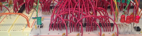
If you’re going to build your own computer, it probably wouldn’t do you well to exactly emulate the computer you’re looking at right now. The modern x86 and x64 chips that power your desktop or laptop contain hundreds of individual instructions, and the supposed RISC CPUs found in ARM-powered devices contain nearly as many. No, if you’re going to build your own computer you should make it easy on yourself, just as [Jack Eisenmann] did  when he built the DUO Compact, a one-instruction set computer made on a breadboard.

Instead of dozens or hundreds of individual instructions, a one instruction computer has – like its name implies – only one way of manipulating bits. For the DUO Compact, [Jack] chose a NOR and fork conditionally instruction. Each line of assembly written for the DUO Compact has four memory instructions: a source address, destination address, skip address 1, and skip address 2. [Jack] explains exactly how this operation can allow him to compute everything:

Three steps occur when executing the instruction:

  1. Load the byte at the first and second address. NOR these bytes together.
  2. Store the result of step 1 in the second address.
  3. If the result of step 1 was zero, then skip to the instruction at the fourth address; otherwise, skip to the instruction at the third address.

As if designing a one instruction computer built using only basic logic and memory chips wasn’t impressive enough, [Jack] went as far as writing an emulator for his system, a compiler, an operating system, and even a few programs such as a square root calculator and a text-based adventure game.

By any measure, [Jack] has finished an amazing build, but we’re blown away by the sheer amount of documentation he’s made available. He’s even gone so far as to write a tutorial for building your own DUO Compact.

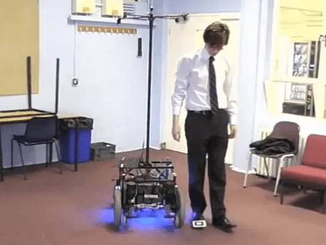
You can check out a few videos of the DUO Compact after the break. Of course, if you’re looking for a project to tackle, you’re more than welcome to design a PCB from the DUO Compact schematic. We’d certainly buy one.

Continue reading “Mess Of Wires Is Actually A One Instruction Computer”