Don’t Tempt The Demo Gods

Including a live technical demonstration as part of a presentation is a lot like walking a tightrope without a net. Which isn’t to say that we don’t do it — we just keep our fingers crossed and bring our lucky horseshoe. The demo gods have smote [Quinn] a mighty blow, in front of a class at Stanford, no less.

IMG_1873-600x448

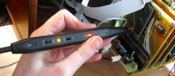
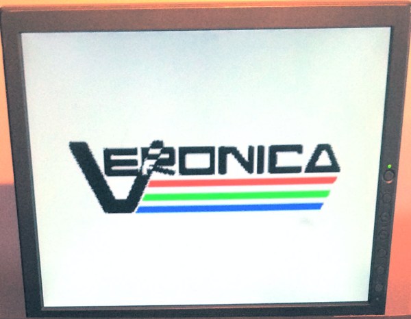
[Quinn]’s scratch-built computer, Veronica, failed to boot in front of a hall of eager students. When the pressure was off, in the comfort of her own lab, [Quinn] got to debugging. You should read her blog post if you’re at all interested in retrocomputing or troubleshooting of low-level hardware bugs. But if you just can’t spare the five minutes for a pleasant read, here’s a spoiler: watch out for flaky card-edge connectors. All’s well that ends well, with a game of pong.

We’ve been following Veronica from her very first clock cycles, so we’re happy to see her back on her feet again. Good job, [Quinn]!

Hackaday 10th Anniversary: Quinn Dunki And Veronica

In case you haven’t been reading Hackaday for the last few weeks, we just had an amazing 10th anniversary party in Pasadena this weekend, full of workshops, talks, and a party that reportedly went until four in the morning. One of the amazing hackers we invited to give a talk was [Quinn Dunki], creator of Veronica, the modern 6502 computer stuffed inside an old radio.

We first saw Veronica a few years ago, but [Quinn] figures she’s been building her computer for about five years now. She’s a software developer by trade that decided one day to dip her toes into the murky seas of hardware development and build a computer from the ground up. She chose the 6502 as the brains of her contraption, laid out everything on single-sided boards etched in a kitchen, and connected everything with a backplane. Right now it has a USB keyboard, (technically a PS/2 keyboard with a USB plug), NES controllers, a VGA display, and a monitor and Pong in ROM. [Quinn]’s goal was to build a computer that could program itself, and after five years, she’s accomplished that goal.

[Quinn] admits her software background was responsible for a few of her admittedly bad design choices; the VGA is generated by an ATMega microcontroller, working under the theory that if she could clock the micro fast enough, she could do VGA. She now believes an FPGA would have been a better choice for video output, but now that the video circuit is done, she probably won’t revisit that problem.

There is one thing missing from Veronica, and something that [Quinn] will be working on in the future: mass storage. Right now every program Veronica can run is either stored in ROM or entered via the keyboard. A hard drive is the next problem to solve, either with an SD card, or a Compact Flash or IDE hard drive.

Veronica Gets A ROM Monitor

monitor

[Quinn] has been on Veronica, her 6502-based computer for quite a while now, but until very recently it’s been more of an embedded project rather than a fully functional computer. Writing software for Veronica on Veronica has been the goal from the start, and finally [Quinn] can write code from a ROM monitor.

In its most basic state, a ROM monitor is an extremely simple piece of software. It resides on the ROM of a computer and is the first thing the computer loads on booting, allowing the user to inspect, read, and write to memory locations, writing code in hex, and running it straight from the monitor.

To write the ROM monitor (and a few other programs), [Quinn] is using the awesome cc65 6502 C compiler. This comes with a whole bunch of macros that make it easy to read keyboard input, shove bits into her AVR GPU, and writing to memory. The monitor program is loaded onto her ROM chip which is automatically read every time the reset button is pressed.

In the video below, you can see [Quinn] writing a few bits to address $2000 that tell the CPU to output ASCII characters to the display. It’s not much, but it’s the first time [Quinn] has written code for Veronica on Veronica, and should prove to be the beginning of a very interesting system.

Continue reading “Veronica Gets A ROM Monitor”

Testing The Limits Of Home PCB Etching

[Quinn Dunki]’s Veronica, a homebrew computer based on the 6502 CPU, is coming along quite nicely. She’s just finished the input board that gives Veronica inputs for a keyboard and two old Nintendo gamepads. [Quinn] is building this computer all by her lonesome, including etching all the PCBs. She’s gotten very, very good at etching her own boards, but this input board did inspire a few facepalming moments.

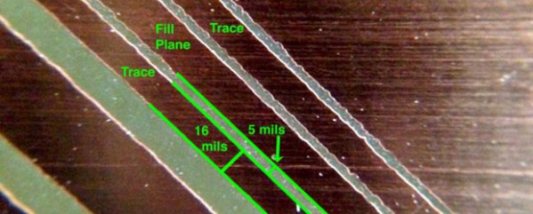
In an earlier post, [Quinn] went over her PCB etching capabilities. As demonstrated by the pic above, she’s able to print 16 mil traces with 5 mil separation. This is just about as good as you can get with homebrew PCBs, but it’s not without its problems.

[Quinn] is using a photographic process for her boards where two copies of a mask is printed on an acetate sheet, doubled up, and laid down on a pre-sensitized copper board. The requirement for two layers of toner was found by experience – with only one layer of toner blocking UV light, [Quinn] got some terrible pitting on her traces and ground planes.

Two photographic masks means the masks must be precisely aligned. This example shows what happens when the acetate sheets are ever so slightly misaligned. With a 5 mil gap between traces, [Quinn] needs to align the masks to within ±2.5 mils; difficult to do by eye, and very hard once you factor in flexing and clamping them down to the copper board.

Even when this process goes perfectly, [Quinn] is pushing the limits of a laser printer. When printing at 600 dpi, the pixels of the print are about 1.5 mils. While GIMP, printer drivers, and the printer itself have some fancy software to help with the interpolation, [Quinn] is still seeing ‘bumps’ on the edges of perfectly aligned parts. This is one of those things that really makes you step back and realize how amazing fabbing PCBs at home actually is.

With most of the hardware for Veronica out of the way, it’s just about time for [Quinn] to start programming her baby. We’re not expecting a full-blown operating system and compiler, but those NES gamepads are probably crying out for some use.
Veronica Gets A Pair Of Gamepads And A Bugged Chip

veronica

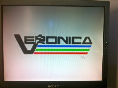
[Quinn Dunki]’s awesome 6502-based computer is coming right along, and she decided it’s time to add one of the most important features found in the 80s microcomputers she’s inspired by – gamepads.

There were two ways of implementing gamepads back in the 80s. The Apple II analog joysticks used a potentiometer for each joystick axis along with a 556 timer chip to convert the resistance of a pot into a digital value. Analog controls are awesome, but a lot of hardware is required. The other option is the Atari/Commodore joystick that uses buttons for each direction. Surprisingly, these joysticks are inordinately expensive on the vintage market but a similar hardware setup – NES gamepads – are common, dirt cheap, and extremely well documented.

[Quinn] wrote a few bits of 6502 assembly to read these Nintendo controllers with Veronica’s 6522 VIA with the help of an ATMega168, and then everything went to crap.

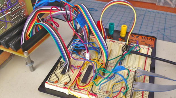
In testing her setup, she found that sometimes the data line from the controller would be out of sync with the clock line. For four months, [Quinn] struggled with this problem and came up with one of two possible problems: either her circuit was bad, or the 6522 chip in Veronica was bad. You can guess which option is correct, but you’ll probably be wrong.

The problem turned out to be the 6522. It turns out this chip has a bug when it’s used with an external clock. In 40 years of production this hasn’t been fixed, but luckily 6502 wizard [Garth Wilson] has a solution for this problem: just add a flip-flop and everything’s kosher. If only this bug were mentioned in the current datasheets…

Now Veronica has two NES controller inputs and the requisite circuitry to make everything work. Video evidence below.

Continue reading “Veronica Gets A Pair Of Gamepads And A Bugged Chip”

Guest Rant: From Bits To Atoms

I’ve been a software developer for quite a while. When you spend long enough inside a particular world, it’s easy to wind up with an ever-narrowing perspective. You start seeing everything from a software point of view. As the saying goes, when your only tool is a hammer, you tend to treat every problem as NP-Complete. Or something. I forget how that goes.

Anyway, the point is, it’s always good to broaden one’s horizons, and solve as many different kinds of problems as possible. To that end, I started to get into hobby electronics recently. The journey has been very enlightening in a number of ways.

Continue reading “Guest Rant: From Bits To Atoms”

How To Debug A Faulty Memory Board

ram

While this is not exactly a hack or a fail, it definitely is an inspiring example on how to debug a faulty card.

[Quinn] is one of the very few hobbyists out there that designed her own 6502 based computer. For the young readers of Hackaday, the MOS 6502 was introduced in 1975 and has been used in the Aple // line, the Commodore 64, the Vic-20, the Atari computers, the Nintendo Enterntainment System and others.

[Quinn]’s homemade new RAM board had been working for many weeks until it started to show some weaknesses by only sporadically passing the boot RAM test. Assuming the RAM was the problem, she started by making a more advanced memory test, which showed errors at random addresses.

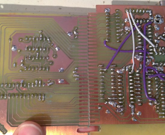
She didn’t have any more of the same memory chips on hand which could be used with a fresh PCB. Determined to power through the issue, she etched a new board with a new memory design. Unfortunately it also gave memory errors at boot. Only one culprit was left, which is shown in the picture above. It’s a small sizing error in the board artwork which was just enough to cause a misalignment on the connector.

The article contains many details about her debugging process, so it definitely is worth the read.