Veronica 6502 Gets Keyboard Input Via USB

PS2

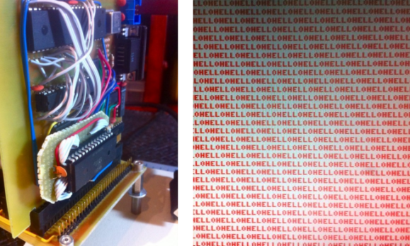
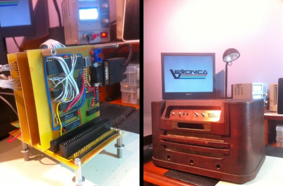
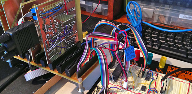
When building a homebrew computer, there are a few milestones that make all the work seem worth it. Of course, seeing the CPU step through address lines on the blinkenlights is near the top, but even more important is being able to type a character on a keyboard and have it show up on a display. [Quinn] didn’t want her Veronica computer to deal with serial terminals or PS/2 keyboards when she typed her first characters in; instead she wanted to read a USB keyboard using 80s-era hardware.

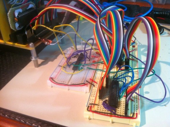
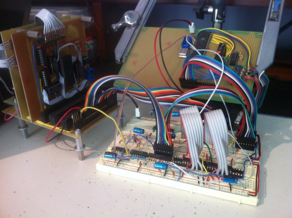
Back in the early days of USB, design specs and keyboard manufacturers included a legacy mode in nearly every USB keyboard ever manufactured. This allows a USB keyboard to work with the ancient PS/2 protocol. [Quinn] tapped into that functionality nearly every PS/2 keyboard has using a 6522 Versatile Interface Adapter. This VIA is in the same family of chips as the venerable 6502 CPU that provides GPIO pins and timers.

[Quinn] connected the keyboard connector tapped for PS/2 input to an ATtiny13. This microcontroller reads the scan codes from the keyboards and sends them to the VIA and the rest of Veronica. It’s quite a bit of work to get to this point, but [Quinn] finally has a computer she can type on, the first step to developing software for her homebrew computer.

Building RAM Into Veronica – The 6502 Computer

ram-for-veronica

It seems strange that RAM is being added to a computer so late in the build, but [Quinn Dunki] must have had it in the back of her mind the whole time because it turns out to be a rather painless experience. For those of you keeping score, this makes her Veronica project Turing complete.

The brightly colored rats nest pictured above connects the new components to the 6502 computer backplane seen in the upper left. [Quinn] decided to go with two 32K SRAM modules which need very little in the way of drive hardware (it’s hanging out on the breadboard to the left). The RAM module will simply listen for its address and react accordingly. There is one hitch regarding a two-phase clock and the need to protect the RAM from erroneous data during the first of those phases.

Getting this all to work actually pointed out a bug in the ROM module she had long ago completed. After picking up on the problem she was able to correct it simply by cutting traces and soldering in jumper wires.

Veronica 6502 Computer Reaches Hello World Stage

veronica-hello-world

The screenshot on the right shows [Quinn Dunki’s] computer project displaying a Hello World program. Well, it’s only showing the word Hello right now, but the concept is the same. This proves that native 6502 code is running on the processor and reliably outputting data through its VGA hardware. That’s a welcome achievement after watching so much work go into this project.

But with anything this complex you can’t expect to make progress without finding bugs. And this step in the journey had a pretty big one in store for [Quinn]. After writing the assembly code and loading it into the machine she was dismayed to find that there were dropped characters all over the place. Now she shows a screenshot and says it’s easily recognizable as a race condition — proving she has a bigger brain than us.

The problem is a pair of uninterruptible processes running on the same AVR chip (part of the GPU she built). They are fighting with each other for control of the processor cycles and she fixed it by making the daughter board seen in the image above. It moves one of the time-critical processes out of that single AVR chip to fix the issue by using an IDT7200L FIFO SRAM chip.

Veronica VGA Board Finalized

veronica-vga-board-finalized

The latest update in the Veronica 6502 computer project is this finalized VGA board which now has a home in the machine’s backplane.

We’ve been glued to the updates [Quinn Dunki] has been posting about the project for many months now. Getting the GPU working proved to take quite a bit of time, but we learned a ton just by following along. The video output had humble beginnings way back in March. That breadboarded circuit got complicated very quickly and that was before it was even interfaced with the CPU. As you can see from the image above, etching and populating the GPU board really cleans up the build. We’re sure it’s robust enough to move around at this point. We wonder if she’s planning on showing it off at a Maker Faire or another geeky gathering?

It really has become clear how wise [Quinn] was to design a backplane board early on. It plays right into the modular concept. She was even smart enough to include that SIL pin header on the near side of the board which was used heavily while prototyping this video module.

Interfacing A GPU With A CPU

interfacing-a-gpu-with-a-cpu

[Quinn Dunki] pulled together many months worth of work by interfacing her GPU with the CPU. This is one of the major points in her Veronica project which aims to build a computer from the ground up.

We’ve seen quite a number of posts from her regarding the AVR-powered GPU. So far the development of that component has been happening separately from the 6502 centered CPU. But putting them together is anything but trivial. The timing issues that were so important to consider when developing the GPU get even hairier when it comes writing to the VRAM from an external component. Her first thought was to share a portion of the external RAM between the CPU and GPU as a way to push rendering commands from one to the other. This proved troublesome both in timing and in the number of pins available on the AVR chip. She ended up using something of a virtual register on the AVR chip that can receive commands from the CPU asynchronously. Timing dictates that these commands be written only during vertical blanking so this virtual register also acts as a status register to let the CPU know when it can send the next command.

Her post is packed with the theory behind the design, timing tests on the oscilloscope, and a rather intimidating schematic. But the most important part is the video showing her success in the end.

Macro Assembly For AVR Chips

avr-macro-assembly

Here’s an interesting tip that can help improve your ability to write assembly code. In an effort to remove the complexity of assembly code for an AVR project [Quinn Dunki] figured out how to use macros when writing AVR code with the GNU toolchain. Anyone using AVR-GCC should keep this in mind if they ever want or need to pound out a project in assembly language.

If you look at the code snippet above you’ll see two commands that are obviously not assembly; PulseVRAMWrite and DisableVRAMWrite. These are macros that direct the assembler to roll in a hunk of code. But avr-as, the assembler used with this toolchain, lacks the ability to handle macros. That’s too bad because we agree with [Quinn] that these macros make the code easier to read and greatly reduce the probability of error from a typo since the code in the macro will be used repeatedly.

The answer is to alter the makefile to use GNU M4. We hadn’t heard of it, but sure enough it’s already installed on our Linux Mint system (“man m4” for more info). It’s a robust macro processor that swaps out all of her macros based on a separate file which defines them. The result is an assembly file that will play nicely with avr-as.

Her implementation is to help in development of the GPU for her Veronica computer project.

Fortifying Veronica’s VGA Output

[Quinn Dunki] just moved to a new work space and had to pack up her homebrew computer project — called Veronica — in the process. She just unboxed it again and decided now was a good time to fortify the VGA display hardware. It wasn’t in the greatest of shape, since everything for the initial video tests had been built on a breadboard. The transition to protoboard ended up turning out just swell.

One of the thing’s that we like best about [Quinn’s] hacks is that she documents her failures (or perhaps we should just call them hiccups?) just as much as she does her successes. This is not a small thing. We understand, because our own screw-ups don’t usually get photographed due to our raging need to just make the frakking thing work.

Once she had moved all the components to the new board the circuit was amazingly organized. Since she’s doing high-speed switching with the VGA signals it was important to keep the lines as short and straight as possible, hence the SRAM stack seen above. But when it was first fired up she had a jumble of only-somewhat-organized color stripes. It turns out that she had forgotten to change the color register in the AVR code, the color lines were hooked up in the wrong order, and the switch mode supply was injecting noise into the system. But thanks to her documentation of these issues we’ll know what to do when we find ourselves in a similar situation.