Building Transistors With Transistors

Since the 1940s when the first transistor was created, transistors have evolved from ornery blocks of germanium wrangled into basic amplifiers into thousands and thousands of different devices made of all kinds of material that make any number of electrical applications possible, cheap, and reliable. MOSFETs can come in at least four types: P- or N-channel, and enhancement or depletion mode. They also bear different power ratings. And some varieties are more loved than others; for instance, depletion-mode, N-channel power MOSFETs are comparatively scarce. [DeepSOIC] was trying to find one before he decided to make his own by hacking a more readily available enhancement-mode transistor.

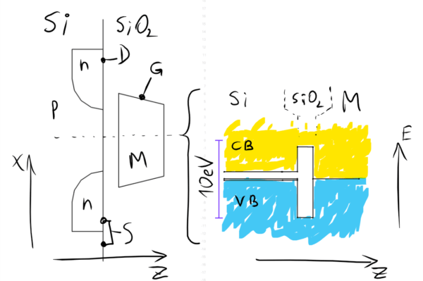
For those not intimately familiar with semiconductor physics, the difference between these two modes is essentially the difference between a relay that is normally closed and one that’s normally open. Enhancement-mode transistors are “normally off” and are easy to obtain and (for most of us) useful for almost all applications. On the other hand, if you need a “normally on” transistor, you will need to source a depletion mode transistor. [DeepSOIC] was able to create a depletion mode transistor by “torturing” the transistor to effectively retrain the semiconductor junctions in the device.

If you’re interested in semiconductors and how transistors work on an atomic level, [DeepSOIC]’s project will keep you on the edge of your seat. On the other hand, if you’re new to the field and looking to get a more basic understanding, look no further than these DIY diodes.

Isolated Voltage Measurements Through Frequency

This one’s not a flashy hack, it’s a great piece of work and a good trick to have up your sleeve. Sometimes you’ve got a voltage difference that you’d like to measure, but either the ground potential is at a different level, or the voltages are too high for your lowly microcontroller.

There are tons of tricks with resistive voltage dividers that you can play. But if you want serious electrical isolation from the target, there’s only one way to go — an optocoupler. But optocouplers only really transmit digital signals, and [Giovanni Carrera] needed to measure an analog voltage.

VFC+calibration

Enter the voltage-to-frequency IC that does just what it says: produces a square wave with a frequency that’s proportional to the voltage applied. Pass this square wave through an optocoupler, and you can hit one side with voltages approaching lightning strikes without damaging the microcontroller on the other side. And you’re still able to measure the voltage accurately by measuring the frequency on the digital I/O pins of the microcontroller.

[Giovanni] built up and documented a nice circuit. He even tested it for linearity. If you’re ever in the position of needing to measure a voltage in a non-traditional way, you’ll thank him later.

“Who Is John Galt?” Finally Answered

For those who haven’t read [Ayn Rand’s] philosophical tome Atlas Shrugged, there’s a pretty cool piece of engineering stuffed in between the 100-page-long monologues. Although fictional, a character manages to harness atmospheric static electricity and convert it into kinetic energy and (spoilers!) revolutionize the world. Harnessing atmospheric static electricity isn’t just something for fanciful works of fiction, though. It’s a real-world phenomenon and it’s actually possible to build this motor.

who-is-john-galt-thumbAs [Richard Feynman] showed, there is an exploitable electrical potential gradient in the atmosphere. By suspending a tall wire in the air, it is possible to obtain voltages in the tens of thousands of volts. In this particular demonstration, a hexacopter is used to suspend a wire with a set of needles on the end. The needles help facilitate the flow of electrons into the atmosphere, driving a current that spins the corona motor at the bottom of the wire.

There’s not much torque or power generated, but the proof of concept is very interesting to see. Of course, the higher you can go the more voltage is available to you, so maybe future devices such as this could exploit atmospheric electricity to go beyond a demonstration and do useful work. We’ve actually featured the motor that was used in this demonstration before, though, so if you’re curious as to how a corona motor works you should head over there.

Continue reading ““Who Is John Galt?” Finally Answered”

Adding A Battery Gauge To A Project With Zero Parts

The typical way of doing a low battery detector is throwing a comparator in the circuit, setting it to measure a certain threshold voltage, and sending that signal off to a microcontroller or other circuit to notify someone the battery is going dead. [Josh] has a simpler way using an 8-bit AVR and zero other parts.

The chip [Josh] is using is the ATtiny84. The ADC in this chip is usually used to measure an unknown voltage against a reference voltage. The trick [Josh] is using is to do this in reverse: The internal 1.1 Volt reference voltage is measured against an unknown scale, namely the input voltage.

The value provided by the ADC on the chip will always be Vin times 1024 over the reference voltage. Since Vin will be 1.1 V in this case, the ADC value is known, it’s only a matter of doing some 6th grade algebra to determine the value of the input voltage.

[Josh] put together a small demonstration where the chip blinks out the number of volts its receiving from a bench power supply. By blinking a LED, it can blink out the current value of VCC as integers, but by using this technique you should be able to get a fairly fine-grained reading of what VCC actually is. Video below.

Continue reading “Adding A Battery Gauge To A Project With Zero Parts”

Afroman Demonstrates Boost Converters

If you need to regulate your power input down to a reasonable voltage for a project, you reach for a switching regulator, or failing that, an inefficient linear regulator. What if you need to boost the voltage inside a project? It’s boost converter time, and Afrotechmods is here to show you how they work.

In its simplest form, a boost converter can be built from only an inductor, a diode, a capacitor, and a transistor. By switching the transistor on and off with varying duty cycles, energy is stored in the inductor, and then sent straight to the capacitor. Calculating the values for the duty cycle, frequency, inductor, and the other various parts of a boost converter means a whole bunch of math, but following the recommended layout in the datasheets for boost and switching converters is generally good enough.

boostconverter

[Afroman]’s example circuit for this tutorial is a simple boost converter built around an LT1370 switching regulator. In addition to that there’s also a small regulator, diode, a few big caps and resistors, and a pot for the feedback pin. This is all you need to build a simple boost converter, and the pot tied to the feedback pin varies the duty cycle of the regulator, changing the output voltage.

It’s an extremely efficient way to boost voltage, measured by [Afroman] at over 80%. It’s also exceptionally easy to build, with just a handful of parts soldered directly onto a piece of perfboard.

Video below.

Continue reading “Afroman Demonstrates Boost Converters”

AC Vs DC Human Pain Test

AC-vs-DC-human-pain-test

Ever wondered just how much being zapped by electricity hurts? Curious if AC is worse than DC? Want to know just how many volts a human body can take? Although many people might cringe at the shear thought of it, [Mehdi Sadaghdar] is an electrical engineer who decided to turn himself into a human guinea pig and find out.

[Mehdi] measured the electrical resistance of his dry skin, his wet skin, and finally his tongue.  He found that his tongue had the least resistance, so it would feel the electricity at much lower levels. Using a bench power supply, he then used his tongue as a testing ground – slowly turning the voltage up and up until he could no longer take the pain. He tested the levels at which: he could first feel the electricity, when it began to get annoying, when it felt like torture, and when he could no longer stand the pain. He tried both AC and DC, and reports that AC is much worse.

Check out the informative, yet admittedly hilarious at times, video after the break. [Mehdi] seems like one awesome engineer! Remember – don’t try this at home.

Continue reading “AC Vs DC Human Pain Test”

From The Readers: Low Battery Cutoff Solutions

We got a lot of really great feedback about low battery cutoff options in the comments section of Monday’s replacement battery post. To refresh your memory, some power tool batteries were replaced by Lithium Polymer units which can be damaged if drained too low before recharging. We had thought that many Lithium cells had cutoff circuitry these days. The consensus is that these batteries didn’t because they’re for RC applications where weight is an issue. But we did get a ton of people sending in commercially available drop-in solutions, mostly from RC hobby outlets, so search around for those if you’re interested.

[Christopher] sent us a link to the cutoff circuit he built for his bike light. You can see the schematic for it above (direct link). He sourced an ATtiny45 to drive a MOSFET which disconnects the battery when it gets too low. This would be easy to adapt to other uses, but note that there’s a voltage regulator involved as well as a few other passives… not a difficult solution but also not all that simple.

This same concept can be adapted. A few commentors mentioned using a transistor (or MOSFET) with the base driven by a voltage divider including a zener diode. This way the voltage rating of the diode would effectively shut off the gate when that threshold was reached.

We also enjoyed reading about [Bill’s] human-controlled cutoff circuit. It also uses a zener diode, but this time in series with a resistor and and LED patched into the trigger of the tool. The LED will shine brightly when the battery is in good shape. It will dim near the end, and fail to light when the critical limit has been reached. Just make sure you’re paying attention and you’re in good shape.