[Darlan Johnson] was working on a wearable project and needed a way to measure the change in voltage and current over time.
Most measurement tools are designed to take snapshots of a system’s state in a very small window of time, but there are few common ones designed to observe and log longer periods. It’s an interesting point, for example, many power supply related failures such as resets occur sporadically. Longer timescale measuring devices could pick these up.
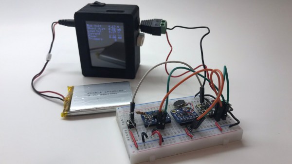
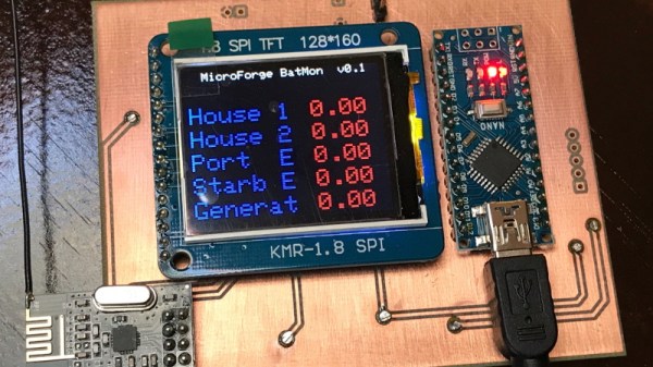
[Darlan] had a ton of Feathers and shields lying around, and combined them into the needed instrument. An INA219 current sensor records the measurements. They are then displayed on a TFT and logged to an SD card. Everything is bundled into a neat 3D printed case along with a battery for wireless operation. A set of barrel connectors provide the breakout to split the wires for the current measurement.
It’s a neatly done hack and we can see it as a nice addition to any hacker’s measurement drawer.


 . The rationale behind this strange averaging procedure is that the resulting number can be used in calculating average power for AC waveforms through simple multiplication as you would for DC voltages. If that answer isn’t entirely satisfying to you, read on. Hopefully we’ll help it make a little more sense.


