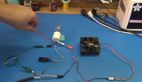
Light Bulb, Diode, And Capacitor Step Mains Down To 12V DC

[Todd Harrison] needed a way to run a 12 volt PC fan from mains voltage. Well, we think he really just needed something to keep him occupied on a Sunday, but that’s beside the point. He shows us how he did this in a non-traditional way by using the resistive load of an incandescent light bulb, a diode, and a capacitor to convert voltage to what he needed. You can read his article, or settle in for the thirty-five minute video after the break where he explains his circuit.

The concept here is fairly simple. The diode acts as a half-wave rectifier by preventing the negative trough of the alternating current from passing into his circuit. The positive peaks of the electricity travel through the light bulb, which knocks down the voltage to a usable level. Finally, the capacitor fills the gaps where the negative current of the AC used to be, providing direct current to the fan. It’s easy to follow but the we needed some help with the math for calculating the correct lightbulb to use to get our desired output current.

Continue reading “Light Bulb, Diode, And Capacitor Step Mains Down To 12V DC”

Automotive Battery Voltage Monitor

car_battery_voltage_monitor

[Rajendra’s] car had just about all the bells, whistles, and gauges he could dream of, but he thought it was missing one important item. In an age where cars are heavily reliant on intricate electrical systems, he felt that he should have some way of monitoring the car’s battery and charging system.

To keep tabs on his car’s electrical system, he built a simple device that allows him to monitor the battery’s instantaneous voltage when the car is powered off, as well as the charging voltage across the battery when the car is running. A PIC16F1827 runs the show, using a simple voltage divider network to step the input voltage down to an acceptable level for use with the PIC’s A/D conversion channel. The resultant measurements are output to a four digit 7 segment display, mounted on the front of the device.

He says that the voltage monitor works quite well, and we’re sure he feels a lot better about the health of his car’s charging system. For anyone interested in keeping closer tabs on their car, he has a circuit diagram as well as code available on his site.

Adjustable Voltage And Polarity Tester

polarity_tester

Instructables user [Rudolf] wrote in to share a handy little tool he created with ham radio operators in mind. Now and again, he found himself connecting to an unknown power supply, and rather than blow out all his expensive radio gear, he decided to put together a simple polarity and voltage tester that can be easily carried out in the field.

The tester features a pair of powerpole connectors, which are used quite often for connecting HAM gear. A PIC12F675 runs the show, acting as an adjustable comparator for detecting voltage levels. By default, his probe glows amber when the supply voltage is below 11.5V, turning green when the supply is between 11.5V and 15V. When the detected voltage is too high, the built-in LED glows a bright red. When the polarity is reversed, the LED flashes red regardless of the supply voltage.

All of these trigger levels can be set in the PIC’s code, which [Rudolf] is kind enough to include on his page, along with schematics for making your own.

PIC Programmable Power Supply

This programmable power supply is the perfect addition to your bench tools. [Debraj Deb], who previously built a whole house power monitor, designed this build around a PIC 18F4520 microcontroller. The desired voltage is set with an attached keypad, resulting in a digital output on the 8-bits of port D. The port connects to another protoboard with an R-2R digital-to-analog converter resulting in the target voltage. A set of transistors amplifies the current and a power transistor then takes care of the final output. After the break you’ll find two videos, the first walks us through the hardware and the second demonstrates the device in action, along with measurements of its performance. This certainly provides a lot more functionality than an ATX power-supply conversion.

Update: A big thanks to [Debraj] who sent us a code package as well as the schematic (PDF) used during testing. We’re having trouble getting the code package up for download right now. Check back later, hopefully we’ll have it up soon.

Continue reading “PIC Programmable Power Supply”

LED Battery Level Indicator

[Kc7fys] came up with a this simple battery level indicator. It uses a single LED to display a battery’s voltage; if the voltage exceeds 12V, it glows green. If it is below 11V, the LED glows red. Anything in between generates an orange glow. The meter is built around an LM358 chip per this schematic, but his actual build looks pretty sloppy because of the dead-bug assembly (check out NASA’s pretty version). Nonetheless, it works, so clean it up and build one if you want to put it (or your batteries) to the test.

Tube Amp Monitor


Sparkfun contributor [Pete] really loves tube amps, but he’s a very safety-conscious guy who doesn’t like being electrocuted. This is a problem, since tube amps are usually very high voltage, and a small mistake can be fatal. To deal with this voltage issue, he built a tube amp with a control system built around a 6DOF v3 controller board. The control system is there mainly in case of a failure, automatically shutting off the high voltage transformer in any such event. It has the added benefit of filtering any 60Hz noise from getting into the audio, which happened before he installed the control system.

In addition to regulating power, the controller board also monitors bias points in the output tubes and displays its diagnostics on an LCD. Aside from getting great sound from the tube amp, [Pete] made it look great too, installing colored LEDs under the tubes. We love his design: just because safety comes first it doesn’t mean cool-factor can’t come in a close second.