The Magic Of A Diode Sampler To Increase Oscilloscope Bandwidth

Making an oscilloscope is relatively easy, while making a very fast oscilloscope is hard. There’s a trick that converts a mundane instrument into a very fast one, it’s been around since the 1950s, and [CuriousMarc] has a video explaining it with an instrument from the 1960s. The diode sampler is the electronic equivalent of a stroboscope, capturing parts of multiple cycle of a waveform to give a much-slowed-down representation of it on the screen. How it works is both extremely simple, and also exceptionally clever as some genius-level high-speed tricks are used to push it to the limit. We’ve put the video below the break.

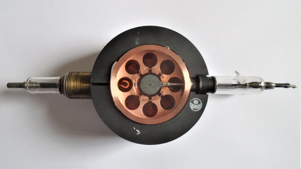
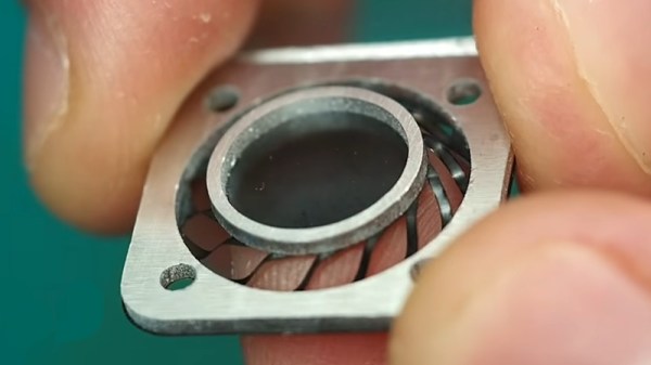
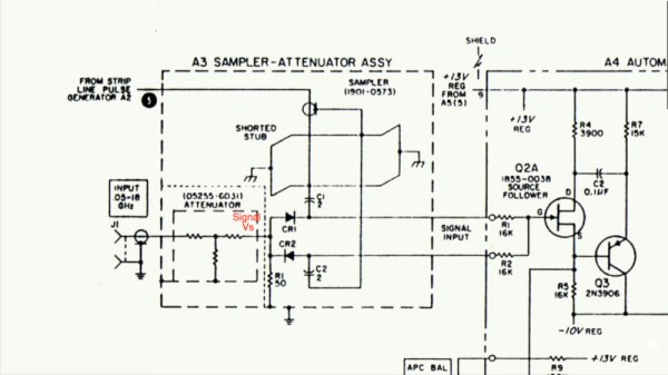
[Marc] has a Keysight 100 MHz ‘scope and the sampler allows him to use it to show 4 GHz. Inside the instrument is a pair of sample-and-hold circuits using fast diodes as RF switches, triggered by very low-rise-time short pulses. Clever tricks abound, such as using the diode pair to cancel out pulse leakage finding its way back to the source. To complete this black magic, an RF-tuned stub is utilized to help filter the pulses and further remove slower components.

It’s slightly amusing to note that the Keysight 100 MHz ‘scope is now “slow” while the early sampling ‘scopes had their “fast” capabilities in that range. The same technique is still used today, in fact, you probably have one on your bench.

The sampler he’s showing us is an accessory for another instrument we’ve previously shown you his work with.

Continue reading “The Magic Of A Diode Sampler To Increase Oscilloscope Bandwidth”

Driving A Motor With An Audio Amp Chip

[InazumaDenki] wanted to answer the question: can you drive a motor with an audio amplifier chip? The answer, of course, is yes. The TDA7052 has a single input, and a bridge output meant to drive a speaker differentially. It should work if the motor doesn’t present more of a load than a speaker.

The plan was to use a resistive divider to provide several discrete voltages to the input. At precisely the half-way mark, there should be no voltage across the load. Altering the input to go higher than halfway should make the motor turn one way, and making it go lower should turn the motor the other way. As you can see in the video below, it does work, although it may not be ideal for this application.

Continue reading “Driving A Motor With An Audio Amp Chip”

Finally, A Machine To Organize Resistors!

Perhaps it’s a side-effect of getting older, but it seems like reading the color bands on blue metal-film resistors is harder than it was on the old brown carbon ones. So often the multimeter has to come out to check, but it’s annoying. Thus we rather like [Mike]’s Resistorganizer, which automates the process of keeping track of the components.

At its heart is a fairly simple concept, with the microcontroller reading the value of a resistor by measuring the voltage from a potential divider. The Resistorganizer extends this using an array of analogue multiplexer chips, and is designed to plug into one side of a breadboard with the idea being that each line can have a resistor connected to earth through it. Of course it’s not quite as simple as that, because to maintain a readable range a set of resistors must be switched in and out to form the other half of the divider for different ranges. Thus another multiplexer chip performs that task.

Finally a set of digital multiplexers handles an LED to see which of the many resistors is currently selected through a pair of buttons, and a dot-matrix LCD display delivers the value. We want one already!

The Device That Won WW2: A History Of The Cavity Magnetron

[Curious Droid] is back with a history lesson on one of the most important inventions of the 20th century: The cavity magnetron. Forged in the fighting of World War II, the cavity magnetron was the heart of radar signals used to identify attacking German forces.

The magnetron itself was truly an international effort, with scientists from many countries providing scientific advances. The real breakthrough came with the work of  [John Randall] and [Harry Boot], who produced the first working prototype of a cavity magnetron. The device was different than the patented klystron, or even earlier magnetron designs. The cavity magnetron uses physical cavities and a magnetic field to create microwave energy.  The frequency is determined by the size and shape of the cavities.

While the cavity magnetron had been proven to work, England was strapped by the war effort and did not have the resources to continue the work. [Henry Tizzard] brought the last prototype to the USA where it was described as “the most valuable cargo ever brought to our shores”. The cavity magnetron went on to be used throughout the war in RADAR systems both air and sea.

Today, many military RADAR systems use klystrons or traveling wave tube amplifiers due to requirements for accurate frequency pulses.  But the cavity magnetron still can be found in general and commercial aviation RADAR systems, as well as the microwave ovens we all know and love.

Check the video out after the break.

Continue reading “The Device That Won WW2: A History Of The Cavity Magnetron”

Input impedance plottet as a function of trace impedance for trace lengths of 1/10, 1/16 and 1/20 of a wavelength. (Credit: Baltic Labs)

When Does Impedance Matching A PCB Trace Become Unavoidable?

A common joke in electronics is that every piece of wire and PCB trace is an antenna, with the only difference being whether this was intentional or not. In practical terms, low-frequency wiring is generally considered to be ‘safe’, while higher frequency circuits require special considerations, including impedance (Z) matching.  Where the cut-off is between these two types of circuits is not entirely clear, however, with various rules-of-thumb in existence, as [Sebastian] over at Baltic Lab explains.

A popular rule is that no impedance matching between the trace and load is necessary if the critical length of a PCB trace (lcrit) is 1/10th of the wavelength (λ). Yet is this rule of thumb correct? Running through a number of calculations it’s obvious that the only case where the length of the PCB trace doesn’t matter is when trace and load impedance are matched.

According to these calculations, the 1/10 rule is not a great pick if your target is a mismatch loss of less than 0.1 dB, with 1/16 being a better rule. Making traces wider on the PCB can be advisable here, but ultimately you have to know what is best for your design, as each project has its own requirements. Even when the calculations look good, that’s no excuse to skip the measurement on the physical board, especially with how variable the dielectric constant of FR4 PCB material can be between different manufacturers and batches.

Heading image: Input impedance plotted as a function of trace impedance for trace lengths of 1/10, 1/16, and 1/20 of a wavelength. (Credit: Baltic Labs)

Continue reading “When Does Impedance Matching A PCB Trace Become Unavoidable?”

Flexure PCB Actuators Made Before Your Very Eyes

When we see something from [Carl Bugeja], we expect to see flexible PCBs and magnets being pushed to do unexpected things. His latest video in which he designs a set of PCB actuators using flexure joints certainly doesn’t fail to please.

His intent is to create a simple actuator in which a magnet is placed over a coil, and moves upward within the confines of he flexure which surrounds it. And rather than try individual designs one after the other he’s created a huge all-in-one test array of different flexure actuators, each having a slightly different design and construction to whichever one is next to it. There are plenty of magnet flips as he tests them, and using this approach he’s quickly able to eliminate the designs which work less well.

To give an idea how these actuators might be best used, he tried them in a few applications. Their lifting force is relatively tiny, but he found them possibly suitable for a haptic feedback device. Of particular interest is that as the structure is a PCB it’s relatively straightforward to run a line to the magnet and turn it into a touch sensor. The idea of an all in one sensor and haptic feedback component is rather appealing, we think.

If you’ve not seen Carl’s work before, we’ve encountered him many times over the years.

Continue reading “Flexure PCB Actuators Made Before Your Very Eyes”

Tiny Spheres Hiding In Your Display

Liquid crystal and Organic LED displays have revolutionized portable computing. They’re also made of glass. Which presents a problem: How do we get electrical signals from fiberglass circuit boards to the glass displays? The answer is double-sided adhesive tape. But we’re not talking about packing tape here. As [Breakingtaps] explains,  this tape has a trick up its sleeve.

The magic is that the tape conducts only in the vertical plane. Even more so, any two conducting sections of the tape are insulated from each other. How does it do that? Magic beans balls, of course!

The tape and adhesive are insulators. Embedded in the adhesive are tiny spheres. The spheres are made of plastic and coated with metal. When the tape (also known as ACF or Anisotropic Conductive Film) is pressed between a PCB with conductors and glass, a few spheres are squished down between the layers. Electrical signals pass between the squished spheres, allowing an image to be displayed on the glass screen. The final step uses heat and pressure to bond the adhesive and cure it. You can also get the material in paste form if you don’t like the tape.

The system works so well that it can be used for connections from a silicon chip directly to the glass.  This is how many display controllers are mounted right to the module — definitely an improvement on the rubber strips used on LCDs of the past.

Continue reading “Tiny Spheres Hiding In Your Display”