
This stunning piece of art is [Emily Velasco’s] take on the Atari Punk Console. It’s a freeform circuit that synthesizes sound using 555 timers. The circuit has been around for a long time, but her fabrication is completely new and simply incredible!
This isn’t [Emily’s] first rodeo. She previously built the mini CRT sculpture project seen to the left in the image above. Its centerpiece is a tiny CRT from an old video camera viewfinder, and it is fairly common for the driver circuit to understand composite video. And unlike CRTs, small video cameras with composite video output are easily available today for not much money. Together they bring a piece of 1980s-era video equipment into the modern selfie age. The cubic frame holding everything together is also the ground plane, but its main purpose is to give us an unimpeded view. We can admire the detail on this CRT and its accompanying circuitry representing 1982 state of the art in miniaturized consumer electronics. (And yes, high voltage components are safely insulated. Just don’t poke your finger under anything.)
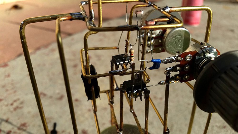 With the experience gained from building that electrically simple brass frame, [Emily] then stepped up the difficulty for her follow-up project. It started with a sound synthesizer circuit built around a pair of 555 timers, popularized in the 1980s and nicknamed the Atari Punk Console. Since APC is a popular circuit found in several other Hackaday-featured projects, [Emily] decided she needed to add something else to stand out. Thus in addition to building her circuit in three-dimensional brass, two photocells were incorporated to give it rudimentary vision into its environment. Stimulus for this now light-sensitive APC were provided in the form of a RGB LED. One with a self-contained circuit to cycle through various colors and blinking patterns.
These two projects neatly bookend the range of roles brass rods can take in your own creations. From a simple frame that stays out of the way to being the central nervous system. While our Circuit Sculpture Contest judges may put emphasis the latter, both are equally valid ways to present something that is aesthetic in addition to being functional. Brass, copper, and wood are a refreshing change of pace from our standard materials of 3D-printed plastic and FR4 PCB. Go forth and explore what you can do!