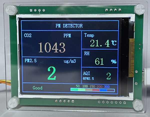
Even though most of the world population couldn’t tell you what room or body temperature is in Fahrenheit, there are some places on this globe where this unit is still in common use. For people in those areas, it’s therefore a real hassle when, say, a cheap Chinese air quality measurement systems only reports in degrees Celsius. Fortunately, [BSilverEagle] managed to patch such a unit to make it display temperature in Fahrenheit.
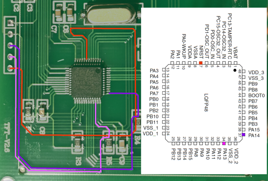 The reverse engineering begins by finding a way to dump the firmware. It’s nice to hear that [BSilverEagle] used some the skills demonstrated in [Eric Shlaepfer’s] PCB reverse engineering workshop from Hackaday Remoticon last November to trace out the debug header and the SWD pins of STM32F103C8 MCU. After that, OpenOCD could be used to dump the firmware image, with no read protection encountered. The firmware was then reverse-engineered using Ghidra, so that [BSilverEagle] could figure out where the temperature was being calculated and where the glyph for the Celsius symbol was stored. From there this it was a straight-forward rewrite of those two parts of the original firmware to calculate the temperature value in Fahrenheit, change the glyph and reflash the MCU.
So why buy this thing in the first place if it didn’t spit out units useful for your current locale? Cost. Buying this consumer(ish) device was about the same cost as buying the individual parts, designing and manufacturing the PCB, and writing the firmware for it. The only downside for their use case was the lack of Fahrenheit. Not a problem for those who demand full control of the hardware they own.
Need a boot camp for using Ghidra? Matthew Alt put together a spectacular video series on Reverse Engineering with Ghidra.