Faux-AI Clapper Almost Seems To Be Listening

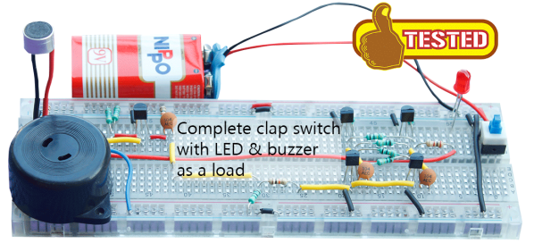
When a job can be handled with a microcontroller, [devttys0] likes to buck the trend and build a circuit that requires no coding. Such was the case with this “Clapper”-inspired faux-AI light controller, which ends up being a great lesson in analog design.

The goal was to create a poor man’s JARVIS – something to turn the workshop lights on with a free-form vocal command. Or, at least to make it look that way. This is an all-analog circuit with a couple of op amps and a pair of comparators, so it can’t actually process what’s being said. “Aziz! Light!” will work just as well as any other phrase since the circuit triggers on the amplitude and duration of the spoken command. The AI-lite effect comes from the clever use of the comparators, RC networks to control delays, and what amounts to an AND gate built of discrete MOSFETs. The end result is a circuit that waits until you finish talking to trigger the lights, making it seems like it’s actually analyzing what you say.

We always enjoy [devttys0]’s videos because they’re great lessons in circuit design. From block diagram to finished prototype, everything is presented in logical steps, and there’s always something to learn. His analog circuits that demonstrate math concepts was a real eye-opener for us. And if you want some background on the height of 1980s AI tech that inspired this build, check out the guts of the original “Clapper”.

Continue reading “Faux-AI Clapper Almost Seems To Be Listening”

Clap On! A Breadboard

The Clapper™ is a miracle of the 1980s, turning lights and TVs on and off with the simple clap of the hands, and engraving itself into the collective human unconsciousness with a little jingle that implores – nay, commands – you to Clap On! and Clap Off! [Rutuvij] and [Ayush] bought a clap switch kit, but like so many kits, this one was impossible to understand; building the circuit was out of the question, let alone understanding the circuit. To help [Rutuvij] and [Ayush] out, [Rafale] made his own version of the circuit, and figured out a way to explain how the circuit works.

While not the most important component, the most obvious component inside a Clapper is a microphone. [Rafale] is using a small electret microphone connected to an amplifier block, in this case a single transistor.

The signal from the microphone is then sent to the part of the circuit that will turn a load on and off. For this, a bistable multivibrator was used, or as it’s called in the world of digital logic and Minecraft circuits, an S-R flip-flop. This flip-flop needs two inputs; one to store the value and another to erase the stored value. For that, it’s two more transistors. The first time the circuit senses a clap, it stores the value in the flip-flop. The next time a clap is sensed, the circuit is reset.

Output is as simple as a LED and a buzzer, but once you have that, connecting a relay is a piece of cake. That’s the complete circuit of a clapper using five transistors, something that just can’t be done with other builds centered around a 555 timer chip.

Inside The Clapper

clapper

Hackaday readers above a certain age will probably remember the fabulously faddish products developed by Joseph Enterprises. These odd gadgets included the Ove’ Glove, VCR Co-Pilot, the Creosote Sweeping Log, and Chia Pet (Cha-Cha-Cha-Chia) as mainstays of late night commercials, but none were as popular as The Clapper, everyone’s favorite sound-activated switch from the 1980s. [Richard] put up a great virtual teardown of The Clapper, that provides a lot of insight into how this magic relay box actually works, along with some historical context for the world The Clapper was introduced to.

Sound activated switches are nothing new, but the way The Clapper did it was just slightly brilliant. Instead of listening to every sound, the mic inside the magic box sends everything through a series of filters to come up with a very narrow bandpass filter centered around 2500 Hz. This trigger is analyzed by a SGS Thompson ST6210 microcontroller ( 4MHz, ~1kB ROM, 64 bytes of RAM, and 12 I/O pins ) to listen for two repeating triggers  within 200 milliseconds. The entire system – including the source code for the MCU – can be seen in the official patent, US5493618.

The Clapper sold many millions of units at a time when a lot of homes were assuredly in a pre-microelectronics world. Yes, in 1986, a lot of TVs had microcontrollers and maybe a washer/dryer combo may have had a few thousand transistors between them. Other than that, The Clapper was many household’s introduction to the ubiquitous computing power we see today, and all with less capability than an Arduino.

LED Matrix Shield Starts With A Very Loud Snap

We see a lot of LED matrix projects. They’re fun, and you can learn a lot of basic lessons during the build. But this one is out of the ordinary. [Rtty21] built an oddly sized, and sound controlled matrix shield for his Arduino. That’s it right there, the shield is the large chunk of protoboard but you can just see the Arduino peeking up over the top of it.

Now we say oddly sized because a 9×9 matrix doesn’t make much sense with an 8-bit micro controller. There’s no schematic but in the clip after the break he mentions that the columns and rows are driven by a decade counter and shift register and that’s what makes it possible to drive nine bits easily. Also of note on the board is that washer above and to the right of the matrix. It’s a touch-sensitive reset button. But the main control mechanism is a Clapper clone circuit. Just snap your fingers and it turns the project on or off. [Rtty21] based the design on this step-by-step sound input build.

Continue reading “LED Matrix Shield Starts With A Very Loud Snap”

Reinventing The Clapper With A Knock-based Home Automation Controller

Clap On!… Clap Off!… was super awesome when The Clapper came out in the mid-eighties. Now [Mathieu Stephan] is trying to make the concept much more functional. He put together a controller that lets you knoch on walls to control things around the house. It’s called the Toktoktok project and uses small boxes to receive user input and control items like lamps and computers.

A piezo element picks up the noises made by a user. Above [Mathieu] demonstrates how sensitive the element is, picking up scratching and knocking anywhere along this wall and displaying it as a waveform on the computer monitor. Clever processing and filtering of these noises lets the device convert them into different commands. He covers all of this in the video after the break, then demonstrates a bunch of functionality such as waking up and starting audio playback from a computer just by tapping on the coffee table.

This isn’t the first time we’ve seen the concept. One of our favorites is this door lock which listens for the secret knock. But [Mathieu] is trying to extend the functionality and bring it to a more general market. Continue reading “Reinventing The Clapper With A Knock-based Home Automation Controller”

DIY Dimmable Clapper For All Your Lazy Lighting Needs

For the lazy man who can’t be bothered to buy a proper wattage lamp here’s the Clever Clapper, a Clapper that finally has the ability to dim the lights.

Like the clapper we saw last month, [Pete]’s version uses an ATtiny2313 and an electret mic. What sets [Pete]’s version apart from the vintage 80s model is the ability to dim the lights. Like any clapper, two hand claps within a second toggles the relay. Clapping three times within one second puts the lamp into fading mode. In this mode, the lights dim up and down with PWM until a fourth clap is detected.

[Pete] saw that the program memory in his ATtiny2313 wasn’t 100% full, so he added a few more capabilities. If you shine a laser onto his circuit, a relay trips and turns on a decorative moon lamp. There’s also a ‘lecture mode’ that feeds the microphone directly into the microcontroller to vary the PWM signal. The result is a light that brightens with more intense sound. Check that feature out after the break after the demo video of [Pete]’s Clever Clapper.

Continue reading “DIY Dimmable Clapper For All Your Lazy Lighting Needs”

DIY Clapper Is The Ideal Gift For The Laziest Person In Your Life

diy-clapper

If you haven’t yet wrapped up your Christmas shopping, you may want to consider building [AlanFromJapan’s] implementation of the ever-classic “Clapper”. With its theme song burned into the brain of anyone old enough to remember the 80s, the clapper was a wonderful device that certainly put the “L” in laziness.

Looking for an excuse to play around with an opamp and microphone [Alan] decided to build his own version of the Clapper based off this similar circuit, which he calls the ClapClap. He built the device using an electret mic that feeds a signal through a small amplifier on the way to the ADC of an ATmega328 microcontroller. The mcu constantly polls the ADC looking for the sound of clapping hands, a solution that works, but isn’t as clean as [Alan] wanted.

He went back to the drawing board, this time building a circuit around an ATtiny2313 microcontroller. Most of the other components remained the same, though the new, smaller design sports some nice PCBs he had made at Seeedstudio. Rather than constantly polling the ADC, this version of the ClapClap looks for peaks in the signal coming from the mic to identify the clapping of hands.

He says that the newer version works great, though he still has a software bug or two that need fixing before he parks himself on the couch for all eternity.