Reaction wheels are useful things, typically used by satellites to keep themselves oriented the right way up in space. Turning the reaction wheel creates an equal and opposite torque in the spacecraft, allowing it to point and rotate itself accurately. The same technique also works here on Earth, and [Brick Experiment Channel] decided to build one out of LEGO to control an inverted pendulum.
The initial design using a small LEGO wheel on an inverted pendulum was only able to work reliably over a 4-degree angle from the vertical. Upgrading the wheel to a larger, heavier one enabled the wheel to instead work over a 28-degree range instead.
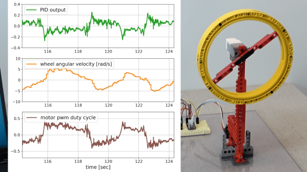
A MPU9250 inertial measurement unit was pressed into service for control of the reaction wheel, fitted to the base of the pendulum and read by a Raspberry Pi. The Pi takes accelerometer and gyroscope readings, and then controls the motor on the pendulum with a PID controller to keep the inverted pendulum upright.
The video goes into a great deal of detail on what it takes to make the pendulum run smoothly. From changes to the control coefficients to measuring the motor’s back EMF, [Brick Experiment Channel] demonstrates everything required to make the pendulum robust to outside perturbances.
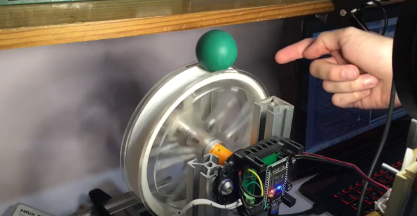
If you march sufficiently deep into the wilderness of control theory, you’ll no doubt encounter the inverted pendulum problem. These balancing acts have emerged with a number of variants over the years, but just because it’s been done before doesn’t mean there’s no space for something new. Here, [David Gonzalez], has taken this classic problem and given it an original own spin–literally–where the balancing act is now a ball balanced precariously upon a spinning wheel. (Video, embedded below.) Mix in a little computer vision for sensing, a dash of brushless motor control, a bit of math, and you have yourself a closed-loop system that’s bound to turn a few heads.
[David’s] implementation is a healthy mix of classic control theory with some modern electronics. From the theory bucket, there’s a state-space controller to drive both the angle and angular velocity of the ball to zero. The “state” is a combination of four terms: the ball angle, the ball’s angular velocity, the wheel angle, and the wheel’s angular velocity. [David] weights each of these terms and sums them together to create an input value to adjust the motor velocity driving the wheel and balance the ball.
From the electronics bin, [David] opted for an ESP32 running Arduino, the custom Janus Brushless Motor Controller running SimpleFOC, and a Maix Bit Microcontroller with an added camera running MicroPython to compute the ball angle. Finally, if you’re curious to dig into the source code, [David] has kindly posted the firmware on Github.
We love seeing folks mix a bit of control theory into an amalgamation of familiar electronics. And as both precision sensors and motor controllers continue to improve, we’re excited to see how the landscape of projects changes yet again. Hungry for more folks closing the loop on unstable systems? Look no further than [UFactory’s] ball balancing robot and [Gear Down for What’s] two wheeled speedster.
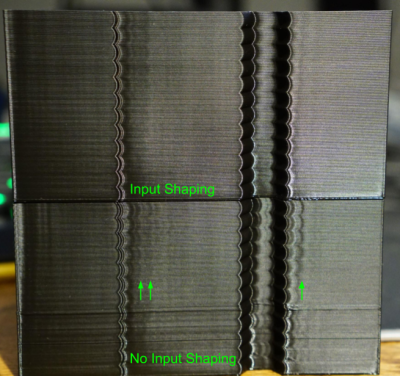
It seems as though we still can’t hit the ceiling on better control schemes for 3D Printers. Input Shaping is the latest technique to land on our radar, a form of resonance compensation that all but eliminates the ghosting (aka: vertical ringing) artifacts we see on the walls of printed parts. While the technique has been around for decades, only recently did [Dmitry Butyugin] both apply it to 3D printer control and merge their hard work into the open source firmware package Klipper. Once tuned, the results are simply astonishing–especially since this scheme can augment the print quality of even the most budget printer.
A Split A/B Test with and without Klipper’s Input Shaping feature courtesy of [@LukesLaboratory]Assuming your 3D printer isn’t infinitely stiff, when your nozzle moves from point to point or changes direction, it vibrates in response to having its speed altered. The result is that the nozzle wobbles along the ideal path it’s trying to track. The result is ghosting, an aesthetic blemish that looks like vertical waves on the sides of your printed part.
Input Shaping is a feed-forward controls technique for cancelling the mechanical vibrations that create ghosting. The idea is that, if we wanted to move the machine from point to point, we send it two impulses. The first impulse kicks the machine into moving and the second impulse follows up at a precise time to cancel the vibrations we would see when the machine comes to a stop. Albeit, moving any machine by sending it two impulses is pretty crude, so we take these impulses, adjust their amplitudes so that they sum to 1, and convolve them with a control input signal that we’d actually like to send it. The result is that the resonance cancellation part of the signal seamlessly “mixes” into the control input signal, and the machine moves from point to point with significantly less vibration at the end of the travel move. For more info on the maths behind this process, have a look at the first four pages of this paper from [Singh and Singhose].
The only hiccup is that you need to do some up-front system characterization of your 3D Printer running Klipper before you can take advantage of this technique. Thankfully the Klipper update comes with a set of step-by-step instructions for characterizing your machine up-front. After a couple test prints to measure the periodicity of your ringing, you can simply apply your measurement results to your config file, and you’re set.
Input Shaping is a prime example of “just wrap a computer around it!“–fixing hardware by characterizing and cancelling unwanted behaviors with software. If you’re hungry for more clever, characterized hardware control schemes, look no further than this Anti-Cogging algorithm for BLDC Motors. And for a video walkthrough of the Klipper implementation, have a look at [eddietheengineer]’s breakdown after the break.
Does your 3D Printer run Klipper? We’d love to see some of your Input Shaping results in the comments.
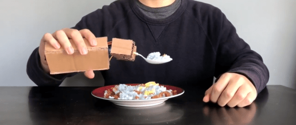
When we first saw [Barqunics’] design for a self-stabilizing spoon for people suffering from Parkinson’s disease, we wondered how well something like that could work. But take a look at the video below and you’ll see this does a fine job of responding to the user’s hand movements and keeping the spoon perfectly level through a wide range of motion.
There’s at least one commercial product that attempts to stabilize a spoon in the same way so that people suffering from that affliction can retain a measure of independence. This shows that you don’t need injection molding and factory made boards to prove the concept. An MPU6050 provides sensor information and two servo motors control the spoon using PID control.
PID — short for proportional, integral, derivative — is a way to adjust something to a desired point. For example, consider trying to heat a cup of water to 95 °C. If you simply turn the heater on full blast until you get to 95 °C, the water will actually get hotter because you’ll overshoot. Using PID, the amount of heating provided will depend on how far off you are now (proportional), how far off you’ve been over the long term (integral), and how much change you’ve effected recently (derivative). The same algorithm works for spoon-balancing and many other types of controls.
One of the problems about learning too much control system theory is that you start to realize almost everything is some sort of control system. That’s the case with [Fernando Zigunov]. After observing a Rayleigh-Plateau instability in his kitchen sink, he decided to build a little display piece that shows water apparently defying gravity that he calls The Piddler.
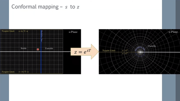
We’ve seen things like this before, of course. A coffee pump, a check valve, and a strobe lamp with a controller is all that it takes. What makes this project interesting is the over hour-long video lecture on the theory behind why this works and how it relates to aliasing and the z-transform. You can check out the video, below.
If we are hiring someone such as a carpenter or an auto mechanic, we always look for two things: what kind of tools they have and what they do when things go wrong. For many types of embedded systems, one important tool that serious developers use is the Kalman filter. It is also something you use when things go “wrong.” [Carcano] recently posted a tutorial on Kalman filter equations that tries to demystify the topic. His example — a case of things going wrong — is when you have a robot that knows how far it is supposed to move and also has GPS coordinates of its positions. Since the positions probably don’t agree, you can consider that a problem with the system.
The obvious answer is to average the two positions. That’s fine if the error is small. But a Kalman filter is much more robust in more situations. [Carcano] does a good job of taking you through the math, but we will warn you it is plenty of math. If you don’t know what a Gaussian distribution is or the word covariance makes you think of sailboats, you are going to have to do some reading to get through the post.
In the late 90s, Volkswagen aired a series of awesome television advertisements that won a few awards relevant to those in advertising circles. One of these ads was titled Synchronicity and showed a VW Jetta’s windshield wipers (among other things) syncing to music as the car drove down a rainy alley. [ch00f] thought beat tracking wipers would make for a great project, and we love the sheer amount of engineering that went into this build.
The build began with [ch00f] taking apart his wiper motor to get some specifics for his build. Ideally, a rotary encoder would be very useful for this project, but designing a durable encoder would be a pain anyway. [ch00f] had to settle with the ‘parking pins’ on the wiper gear motor that allow the wipers to be driven in intermittent mode.
[ch00f] spent a great deal of time writing code that would guarantee a constant wiper speed, but that didn’t solve the problem of phase, or having the wipers begin or end their cycle on the beat. This problem was somewhat solved (as you can see in the video after the break) by using a feed forward system – basically, the software would predict the change in phase needed and correct it by changing the speed.
The build still isn’t perfect, although that’s mainly due to the placement of wiper parking switch on the wiper motor. [ch00f] plans on spending a little more time correcting the wiper speed/phase control with software, but what he’s got now is still very impressive.