Building A Brushless Motor Controller

brushless_motor_controller

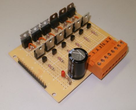
Brushless motors and the way in which they are controlled can be a bit of an enigma to those just starting out in hobby electronics. [Andrew] from spingarage thought it would be helpful to put together a quick tutorial showing how he built a simple brushless motor controller in about a day’s time. He constructs everything on protoboard from components he acquired at RadioShack in order to demonstrate the ease of sourcing parts and building a brushless motor driver.

While he skips most of the theory behind brushless motor control itself, he does touch on the signaling these motors require for movement as well as how motor position is determined. Specifically, he expands on how half-bridges can be used to create the sine wave signaling required by a single motor input, as well as how three of these can be combined to drive a brushless motor.

The post is the first in a series of posts about brushless motors, so we should see some code examples and some practical applications in the near future.

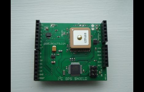
I2C Arduino GPS Shield

i2c_gps_shield

[Wayne] wrote in to share an item he just finished working on, an I2C GPS shield for the Arduino. While other GPS solutions have existed for quite some time, his caught our eye due to its feature list.

The shield removes a good bit of the hassle associated with parsing raw NMEA data from traditional GPS addons. While you have the option to communicate with the GPS module over serial in order to obtain the raw data, the use of the I2C interface makes getting the most commonly used GPS data a breeze. The GPS module itself can be set to update at anywhere from 1 to 10 Hz, and [Wayne] says that the I2C bus blows away the oft-used 9600 baud serial interface. While I2C is primarily used for receiving data, it can also be utilized to configure the GPS via its control registers, allowing for on the fly settings tweaks.

While he does sell the units pre-assembled at a competitive price, [Wayne] also provides a full schematic, making this an easy afternoon project once you have sourced the proper components.

Automated Faucet Keeps Your Cat Watered

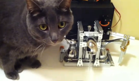
Like many of us [Chris Dillon]’s cat prefers to drink cold fresh water directly from the tap. However, unlike us, [Chris]’s feline buddy is too preoccupied with cat stuff to bother flipping off the faucet after its use. As it turns out, this was an excellent opportunity not only for [Chris] to flex his project muscles, but also to lay the groundwork for future home automation projects.  While most of us may go for a simple solenoid [Chris] had to make the rig completely reversible. The result is an automated  faucet control which involves an infrared sensor, Arduino,  and tight fitting rail system with a servo to operate the sink handle.

After getting all of the hardware and the sensor sorted [Chris] went on to add a data logging PC to the mix. The faucet setup communicates with a Linux server via Xbee modules, and populates a MongoDB database. The setup even allows [Chris] to flag false positives (human sink use for example) and produce charts of his feline friend’s water usage. We suspect the cat will be none too pleased when it gets its water bill.

Don’t forget to check out [Chris Dillon]’s site for details on the project including code and a list of lessons learned. Also, since this is the internet after all, we have several other cat related projects for your viewing pleasure.

[Thanks Chris Burrows (and nephew)]

Check out a video of the setup in action after the jump.

Continue reading “Automated Faucet Keeps Your Cat Watered”

RF Robot Controlled From A Terminal Window

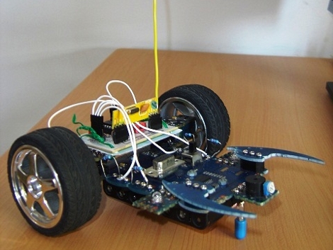
This robot can be controlled from the terminal window of your computer. You can see a manilla-colored board mounted between the wheels. This is the RF receiver which has quite a long antenna that we’ve cropped out to get a better look at the bot itself. [Ashish] picked up an RF transmitter/receiver pair for about $4 and after the break you can watch him walk us through the method he’s using for control.

First off, he had to find a way to interface the transmitter with his computer. He decided to use an Arduino because sending data to it from the computer is as simple as writing to /dev/ttyUSB0. The Arduino sketch just listens for incoming characters on the serial connection and pushes them over the RF transmitter.

We like his development methods. In the video he shows the command syntax used to drive and stop the robot. Once he figured that out he wrote a shell script to send the bot on a preprogrammed square path. From there a bit more coding would give him real-time control which could be extended to something like a web-based interface for smartphone control.

Oh, and if you’re wondering about the bot itself it’s a kit robot which normally uses IR control. [Ashish] upgraded to RF since it doesn’t require line-of-sight to work.

Continue reading “RF Robot Controlled From A Terminal Window”

Turn A Logic Analyzer Into A Signal Generator Using Only Software

One thing we learned by watching [Alton Brown] on all of those Good Eats episodes is that a multitasker is way better than a unitasker. [Joost] is thinking along the same lines by taking a fantastic tool and adding a useful function to it. His software project turns a USB Saleae Logic Analyzer into a signal generator.

There are already a multitude of reasons to own one of these fantastic tools. But the ability to use it to generate up to 8 channels of PWM signals is a welcome addition. It is capable of producing frequencies from 1Hz up to 1MHz at a sample rate of 4 MHz. It uses the original SDK and doesn’t require any changes to the hardware (we would’ve thought new firmware was necessary, but happily that’s not the case). The one caveat is that right now this only works with Windows machines running the .NET version 3.5 or higher. It looks like an MSI installer package is all that’s available for download so the thoughts of easily porting this to other operating systems have been dashed unless [Joost] decides to share his source code.

Edit 7/12/2016: [Joost]’s webpage is down, but he moved it to Github.

Facebook Notifier Uses Some Papercraft And Simple Electronics

This weekend project will tell you when you’ve got something new to look at on your Facebook page (translated). The yellow flag on the side of the mini-mailbox automatically goes up, alerting you to your recent online popularity.

[Rocco’s] craftwork on this project is fantastic. We love the scale, the colors, and especially the artificial grass that adorns the base. Inside the mailbox an Arduino controls a small servo motor attached to the new mail flag. As with other Arduino-based notifiers (be it the Internet Furby, or our own troll sniffing rat) the USB connection makes it incredibly easy to convert online information to real-world signals. The client side of this is a Python script. It uses a package that we were previously unfamiliar with called mechanize. We’ve just made a cursory examination of how that package is used, but we’re going to keep it in mind as an alternative to our usual go-to package, BeautifulSoup, which tends to be a bit hairy when you’re just looking for some basic data.

Generating Pink Noise

[Miceuz] just finished his first surface mount electronics project. It’s a pink noise generator that is used for testing audio equipment (scroll down that link for the English version of his writeup).

Pink noise is somewhere in between red noise and white noise. Didn’t realize there were more colors than just white when it comes to noise? The benefit of testing with pink noise is that it the power of the audio signal is stable through each octave of sound – white noise increases in power with each additional octave which can damage the tweeters in a sound system.

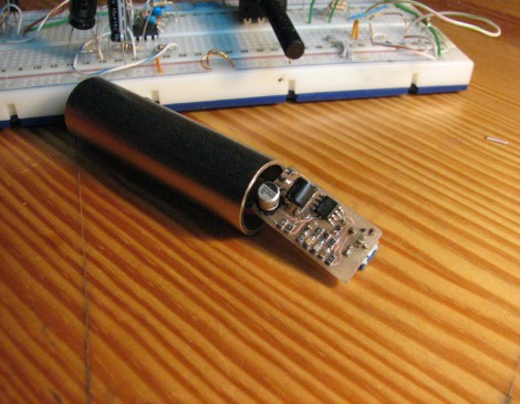
The goal in this design was to build a noise generator that fit into an XLR connector. [Miceuz] started with an existing design, and altered it to suit his needs. Much like a condenser microphone, the pink noise generator uses phantom power instead of a standalone power source. For instance, the design he based this on required two 9v batteries. The size, the choice of case, and the absence of a battery all spell WIN for this project.