USBPIC Controls Just About Anything

Over the last few years, [Michael] has been developing a PIC microcontroller board. He calls his project USBPIC, and with the addition of a few FET drivers, H-bridges, and LED drivers his homemade dev board can handle just about anything thrown at it.

[Michael]’s board is build around a PIC18F2455 microcontroller with both an In Circuit Serial Programming header and support for a USB port included. Instead of going for a modular format where the board can expanded through shields or expansion cards, [Michael] decided to make three different versions of the USBPIC.

The TRANS USBPIC includes eight FETs for switching off high current devices totaling 32 Amps. The MATRIX board has twice as many outputs as the TRANS board, but uses ULN2803 or UDN2982 chips for driving smallish-current devices. Finally, the HBSW board takes a TRANS board and replaces four FETs with a an L298 H-bridge chip for driving two DC motors.

For what [Michael] lost in modularity, we think he gained a very tidy microcontroller board capable of driving everything from robots to LED matrix displays.

Mechanical Donkey Kong Features Laser Cut Mario

[Martin] just sent in a project he’s been working on that takes Donkey Kong out of the realm of pixels and sprites and puts our hero Mario into a world made of laser cut plywood.

This mechanical version of Donkey Kong uses an Arduino stuffed into an old NES to control Mario jumping over ball bearing ‘barrels.’ The game starts with 12 of these barrels ready to be thrown by our favorite gorilla antagonist, which Mario carefully dodges with the help of a pair of servos.

This is only the first iteration of [Martin]’s mechanical version of Donkey Kong. The next version will keep the clever means of notifying the player if Mario is crushed by a barrel – a simple magnet glued to the back of the Mario piece – and will be shown at the UK Maker Faire next year.

Although [Martin]’s ideas for a mechanical version of Donkey Kong aren’t fully realized with this build, it’s already a build equal to electromechanical Pong.

Speech Recognition On An Arduino

Speech recognition is usually the purview of fairly high-powered computers chugging along at hundreds of Megahertz with megabytes of RAM. Bringing speech recognition to the low-power microcontroller you’d find in an Arduino sounds like the work of a mad scientist or Ph.D. candidate, but that’s exactly what [Arjo Chakravarty] did. He developed the μSpeech library for the Arduino to allow for speech recognition for a limited set of voice commands.

Where most speech recognition systems use FFT and very fancy math to determine what phonemes a user is saying, [Arjo]’s system does away with this unnecessary complexity in favor of using very, very basic integral and differential calculus.

From [Arjo]’s user guide for μSpeech (PDF warning) we can see it’s possible to connect a small microphone to the analog input of an Arduino and accept voice commands such as ‘left’, ‘right’, and ‘stop’. The accuracy is pretty good, as well – 80% if μSpeech is trying to recognize words, and 30-40% if μSpeech is programmed to recognize single phonemes.

Sadly we couldn’t find a demo video of μSpeech in action, but you’re more than welcome to grab it via github for your own project. Send us a video of μSpeech in action and we’ll put it up.

Communicating With A Beam Of Light

Last weekend, ARRL, the national association of amateur radio, held a contest called, “10 GHz and up” with the goal of communicating via radio or microwaves over long distances. [KA7OEI] and a few friends decided to capitalize on the “and up” portion of the ’10 GHz and up” contest by setting up a full-duplex voice link over a distance of 95 miles. They used the 478 THz band, also known as red LEDs and laser pointers.

With [Ka7OEI]’s friends [Ron] and [Elaine] perched atop a 5700 foot-high mountain near Park City, Utah, [Gordon], [Gary] and [KA7OEI] trudged up a hill about 10 miles north of Salt Lake City. With the help of a pair of 500,000 candlepower spotlights, the two teams found each other and began pointing increasingly higher power LEDs at each other.

The teams started off with 3 Watt red LEDs before moving up to 30 Watt LEDs and a photodetector at each end. Even though the teams weren’t working with a true line-of-sight – refraction of the atmosphere allowed them to transmit this far – they were able to transmit tone-modulated Morse and even full-duplex voice.

Not bad for a transmission that bends the FCC’s “275 GHz and up” amateur band to its breaking point.

Adding Famicom Audio Channles To An NES Without Messing Up The Console

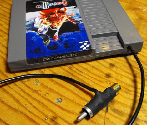
[Callan Brown] wrote in to show us a really interesting NES audio hack. [Callen] decided that he wanted the full Castlevania III audio experience, which (without modifications) can only be had through the original Japanese Famicom console. [Callen] weighed a few adapter options, and instead decided to come up with his own.

The issue is that the Japanese Famicom and the American NES actually have a different cartridge connector. The change in hardware from a 60 pin to a 72 pin connector added “features” like the 10 pins connected directly to the expansion port (used for stuff like the teleplay modem, who knew). The other two additional pins are used by the annoying 10NES lockout chip. While they were at it, Nintendo decided to route the audio path through the expansion connector instead of the cartridge.

This means that the Japanese cartridges can’t pipe sound to the NES audio channel with just a pin adapter. Good news though, after sourcing a pin adapter hidden inside certain NES games (Stack Up, Gyromite), audio can easily just be pulled from the adapter PCB. This requires the more expensive Famicom Castlevania III cartridge (Akumajou Densetsu). To cleanly route the new audio cable out of his front loading NES [Callan] reuses the sacrificial adapter game’s cart to make some kind of unholy hybrid. To round it off [Callan] also goes over steps to flash a translated ROM to the Japanese game.

What difference could an extra two squares and a sawtooth make? Check out the sound comparison video after the jump! Thanks [Callan].

Continue reading “Adding Famicom Audio Channles To An NES Without Messing Up The Console”

Automated Home Brewing System Has An Insanely Professional Controller

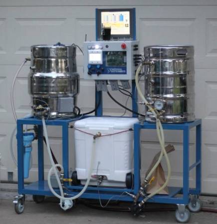
So you know how on Breaking Bad, the chemist [Gale Boetticher] sets up an impressive rig to brew the best cup of coffee? Well what do you think of a group of engineers taking on beer as their side project? This rig, which we do think is pretty insane, is the result of embedded system engineers developing an automated brewing system.

[Ben_B] started from humble beginnings. He built a PID controlled smoker much like the one we saw last Monday. From there he ground out several iterations of brewing hardware, adding a bit of automation at each step along the way. But things really took off when the events department at his company, National Instruments, took notice. They put the team on the task of assembling professional grade control hardware for the unit. And of course while we’re spending the company dime why not chrome those boiling vessels at the same time. The finished project was shown off at a trade show to help promote the company.

The post thread linked at the top has shots of the complicated mounting and wiring that went into the controller. We’re not sure how much intervention is actually necessary during a session. But with all the sensors, pumps, valves, filters, and whatnot we wouldn’t be surprised if all you need to do is pitch some yeast into what comes out of it.

Wiring Up A Lot Of LED Segment Displays

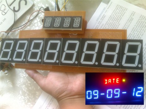
One look at this display and you know there’s a whole lot of pins that need to be wired up. Now look at what those display modules are mounted on. That’s right, [Kemley] is using point-to-point soldering to rig up this big display. It sports four sixteen segment modules on top for alpha-numeric information, and eight large seven segment modules for displaying numbers only.

We’re not certain as to how the electronics are arranged. When talking about the 16-segment modules he mentions that all four are in parallel with NPN transistors to switch the common anode of each. That’s easy enough to understand. But when you get a look at the transistor board you’ll see 24 of them in use. He’s included a 150 ohm resistor on the collector of each transistor. It must be set up to only allow one segment of each group to switch on at a time? We’d guess that each segment is divided into two (upper and lower pins are multiplexed separately), which would explain the double set of transistors. As for date and time, an Arduino board monitors a DS1307 RTC and manages the scanning of the display.