Co-Exist With Your Coax: Choose The Right Connector For The Job

Just a selection from the author's unholy assortment of adaptors.
Just a selection from the author’s unholy assortment of adaptors.

If you do any work with analogue signals at frequencies above the most basic audio, it’s probable that somewhere you’ll have a box of coax adaptors. You’ll need them, because the chances are your bench will feature instruments, devices, and modules with a bewildering variety of connectors. In making all these disparate devices talk to each other you probably have a guilty past: at some time you will have created an unholy monster of a coax interface by tying several adaptors together to achieve your desired combination of input and output connector. Don’t worry, your secret is safe with me.

Continue reading “Co-Exist With Your Coax: Choose The Right Connector For The Job”

DIY Active Sub-GHz Differential Scope Probe

Fancy measurement gear is often expensive to buy, but some bits of kit are entirely DIY’able if you’re willing to put a little work into the project. [Christer Weinigel] needed to get some measurements of a differential clock signal that was ticking away around 500 MHz. El-cheapo probes aren’t going to cut it here. They won’t have the bandwidth and most off-the-rack probes are single-ended, that is they’re referenced to ground. [Christer] needed the difference between two balanced signals, neither of which is grounded. In short, [Christer] needed a high-frequency active differential oscilloscope probe, and they’re not cheap. So he built one himself.

simulation-schematicThe circuit in the probe is really just an instrumentation amplifier design with a modified input stage and a 50 ohm output impedance. (See this article on in-amps if you need to brush up.) With higher frequencies like this, it’s going to be demanding on the op-amp, so [Christer] spent some time simulating the circuit to make sure it would work with his chosen part. Then he made up a bunch of PCB designs and had them made. Actual results matched fairly well with the simulation.

With some minor tweaking on the input damping resistors, he got a tool that’s dead flat up to 300 MHz, and totally usable up to 850 MHz. If you tried to buy one of these, it’d set you back the cost of a few hundred lattes, but this one can be made for the price of one or two if you get the PCBs done cheaply. Of course, the design files are available for your own use. Kudos [Christer].

Edit: By total coincidence, Bil Herd just posted a video intro to differential signals. Go check it out.

And thanks to [nebk] for the tip!

Intel Ups The Dev Board Ante With The Quark D2000

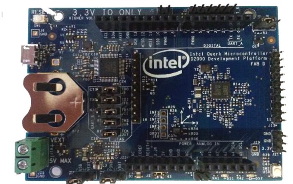
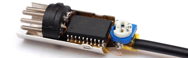
Intel have a developer board that is new to the market, based on their Quark (formerly “Mint Valley”) D2000 low-power x86 microcontroller. This is a micropower 32-bit processor running at 32MHz, and with 32kB of Flash and 8kB of RAM. It’s roughly equivalent to a Pentium-class processor without the x87 FPU, and it has the usual impressive array of built-in microcontroller peripherals and I/O choices.

The board has an Arduino-compatible shield footprint, an FTDI chip for USB connectivity, a compass, acceleration, and temperature sensor chip, and a coin cell holder with micropower switching regulator. Intel provide their own System Studio For Microcontrollers dev environment, based around the familiar Eclipse IDE.

Best of all is the price, under $15 from an assortment of the usual large electronics wholesalers.

This board joins a throng of others in the low-cost microcontroller development board space, each of which will have attributes that its manufacturers will hope make it stand out. Facing such competition the Intel board will have to be something rather special to achieve that aim, so why should it excite your interest? We would point to the low price, the x86 code if that is your flavour of choice, and the relatively tiny power consumption.

Stepping back from the dev board for a moment, consider this processor as an illustration of technological progress in semiconductor fabrication. Over twenty years ago this chip’s Pentium ancestor ran on 5 volts and got so hot you could fry an egg on it, here is a Pentium that can run on a few milliwatts from a coin cell. Fortunately you won’t be running Windows 95 on it though.

We’re sure we’ll see plenty of projects here in the future using the Quark. Intel’s previous effort in this space, the Edison, has made several appearances. We’ve covered its launch in 2014, looked at someone running Doom on it, and examined its use with audio effects.

Thanks [Nolan M] for the tip.

The ATtiny MIDI Plug Synth

MIDI was created over thirty years ago to connect electronic instruments, synths, sequencers, and computers together. Of course, this means MIDI was meant to be used with computers that are now thirty years old, and now even the tiniest microcontrollers have enough processing power to take a MIDI signal and create digital audio. [mitxela]’s polyphonic synth for the ATtiny 2313 does just that, using only two kilobytes of Flash and fitting inside a MIDI jack.

Putting a MIDI synth into a MIDI plug is something we’ve seen a few times before. In fact, [mitxela] did the same thing a few months ago with an ATtiny85, and [Jan Ostman]’s DSP-G1 does the same thing with a tiny ARM chip. Building one of these with an ATtiny2313 is really pushing the envelope, though. With only 2 kB of Flash memory and 128 bytes of RAM, there’s not a lot of space in this chip. Making a polyphonic synth plug is even harder.

The circuit for [mitxela]’s chip is extremely simple, with power and MIDI data provided by a MIDI keyboard, a 20 MHz crystal, and audio output provided eight digital pins summed with a bunch of resistors. Yes, this is only a square wave synth, and the polyphony is limited to eight channels. It works, as the video below spells out.

Is it a good synth? No, not really. By [mitxela]’s own assertion, it’s not a practical solution to anything, the dead bug construction takes an hour to put together, and the synth itself is limited to square waves with some ugly quantization, at that. It is a neat exercise in developing unique audio devices and especially hackey, making it a very cool build. And it doesn’t sound half bad.

Continue reading “The ATtiny MIDI Plug Synth”

Wooden Computer Case Adds A Touch Of Modern

When [LouisVW] decided to build a new gaming rig, he wanted to try something different. So instead of buying a pre-built tower, he made one — out of wood!

Coming from someone who has no experience in 1GNAWU0woodworking (or computer building) we’re seriously impressed with what he’s made. He was originally inspired to build the case when he saw boxes made by stacking pieces of plywood together — he got one and decided to turn it into a case.

Using a jigsaw, chisel and Dremel he was able to cut out all of the fan holes and drive bays fairly easily, and thanks to overlapping plastic covers it wasn’t that hard to make everything look perfect.
Continue reading “Wooden Computer Case Adds A Touch Of Modern”

A Ridiculous Way To Light An LED: Candle-power

If you have ever entertained yourself by reading comprehensive electronic-theory textbooks you’ll have seen references to technologies that sound really interesting but which you will rarely hold in your hand. They may be dead-ends that have been superseded by more recent innovations, or they may be technologies that have found uses but in other fields from those in which they originally showed promise. What if you could take these crazy parts and actually build something?

[Fedetft] has an interesting project that combines two of those intriguing textbook references, he’s created a thermopile that lights an LED through an inverter whose oscillator is a tunnel diode. Dig out the textbook.

If you’ve used a thermocouple thermometer or a semiconductor thermoelectric generator then you’ll have encountered the thermoelectric effect. Perhaps you’ve even operated a Peltier cooling element in this mode. When a circuit is made with two junctions between different types of conductor with a temperature difference between the two junctions, a current will flow in the circuit which is dependent on both the scale of the temperature difference and the properties of the conductors.

A thermopile is a collection of these thermoelectric junction circuits between metal conductors, arranged in series to increase the voltage. [Fedetft]’s thermopile uses chromel and alumel wires taken from a K-type thermocouple. He’s made six sets of junctions, and supported them with small pieces of mica sheet. Using the heat from a candle he found he could generate about 200mV with it, at about 3.7mW.

The RCA tunnel diode inverter circuit

Such a tiny source of electricity would be of little use to light an LED directly, so he needed to build an inverter. And that’s where the tunnel diode comes in. Tunnel diodes have a negative-resistance region that can be used to amplify and oscillate at extremely high frequencies in extremely simple circuits, yet they’re not exactly a device you’d encounter very often in 2016. [Fedetft] has a Russian tunnel diode, and he’s used it with a toroidal transformer in an inverter circuit he found in an RCA tunnel diode manual from 1963. It’s a two-component Joule Thief. The RCA manual is a good read in itself for those curious about tunnel diodes.

The resulting circuit produces a 15kHz oscillation with 4.5v peaks, and has just enough power to light an LED.

While it might seem pointless to barely light an LED from a brightly lit candle, the important part of [Fedetft]’s project is to gain some understanding of two of those technological backwaters from the textbooks. And we applaud that.

It’s the mark of a truly esoteric technology that it features rarely on Hackaday, and neither of these two disappoint. We’ve only mentioned tunnel diode in passing when looking at diodes in general, and we’ve tended to use “thermopile” in another sense to refer to thermal imaging cameras.

An Excellent Primer For Sketching Mechanical Drawings

Mechanical drawings are an excellent way to convey design information, and while sophisticated 3D modeling is slowly taking over, with some companies accepting files over drawings, the mechanical drawing remains the written contract so to speak for complex parts with tolerances and non-modeled features.

But if you didn’t take a technical drawing class (typically Engineering Drawings 101), how do you learn? Well, if you have 15 minutes, this is an excellent video, which speaking from experience, covers the basics from the 101 course.

The lesson covers all the basics, from 2D projection, multi-view drawings, isometric projection, cross sectioning, linear dimensioning, basic tolerancing and alternate views.

Continue reading “An Excellent Primer For Sketching Mechanical Drawings”