Putting Crimpers To The Test: How Good Are Our Crimp Tools?

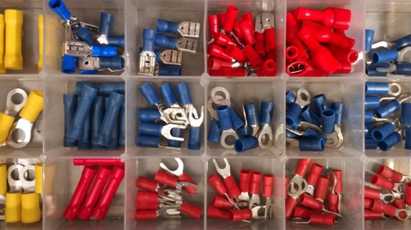
Almost every project of mine from the last quarter century, if it has contained any wiring, has featured somewhere at least one crimp connector. There are a multiplicity of different types of crimp, but in this case I am referring to the ubiquitous variety with a red, blue, or yellow coloured plastic sleeve denoting the wire size they are designed for. They provide a physically robust and electrically sound connection that is resistant to wire fatigue due to vibration, and that can carry hefty currents at high voltages without any problems.

You might expect this to now head off into the detail of crimp connection, but my colleague Dan has already detailed what makes a good or a bad crimp. Instead recently my constant searches for weird and wonderful things to review for your entertainment led me to a new crimp tool, and thence to a curiosity about the effectiveness of different styles of tool. So I’m going to evaluate the three different crimping methods available to me, namely my shiny new ratchet crimp pliers, my aged simple crimp pliers, and for comparison an ordinary pair of pliers. I’ll take a look at the physical strength of each crimping method followed by its electrical effectiveness, but first it’s worth looking at the tools themselves.

Continue reading “Putting Crimpers To The Test: How Good Are Our Crimp Tools?”

No Caffeine, No Problem: A Hand-Soldered Chip-Scale Package

It’s said that the electronic devices we use on a daily basis, particularly cell phones, could be so much smaller than they are if only the humans they’re designed for weren’t so darn big and clumsy. That’s only part of the story — battery technology has a lot to do with overall device size — but it’s true that chips can be made a whole lot smaller than they are currently, and are starting to bump into the limit of being able to handle them without mechanical assistance.

Or perhaps not, if [mitxela]’s hand-soldering of a tiny ball-grid array chip is any guide. While soldering wires directly to a chip is certainly a practical skill and an impressive one at that, this at least dips its toe into the “just showing off” category. And we heartily endorse that. The chip is an ATtiny20 in a WLCSP (wafer-level chip-scale package) that’s a mere 1.5 mm by 1.4 mm. The underside of the chip has twelve tiny solder balls in a staggered 4×6 array with 0.4 mm pitch. [mitxela] tackled the job of soldering this chip to a 2.54-mm pitch breakout board using individual strands from #30 AWG stranded wire and a regular soldering iron, with a little Kapton tape to hold the chip down. Through the microscope, the iron tip looks enormous, and while we know the drop of solder on the tip was probably minuscule we still found ourselves mentally wiping it off as he worked his way across the array. In the end, all twelve connections were brought out to the protoboard, and the chip powers up successfully.

We’re used to seeing [mitxela] work at a much larger scale, like his servo-plucked music box or a portable Jacob’s Ladder. He’s been known to get small before though, too, like with these tiny blinkenlight earrings.

Continue reading “No Caffeine, No Problem: A Hand-Soldered Chip-Scale Package”

Everything You Didn’t Know You Were Missing About Bias Tees

Do you need a bias tee? If you want to put a DC voltage on top of an RF signal, chances are that you do. But what exactly are bias tees, and how do they work?

If that’s your question, [W2AEW] has an answer for you with this informative video on the basics of bias tees. A bias tee allows a DC bias to be laid over an RF signal, and while that sounds like a simple job, theory and practice often deviate in the RF world. The simplest bias tee would have a capacitor in series with the RF input and output to pass AC but block DC from getting out the input, and a DC input with a series inductance to prevent RF from getting into the DC circuit. Practical circuits are slightly more complicated, and [W2AEW] covers all you need to know about how real-world bias tees are engineered. He also gives some use cases for bias tees, from sending DC signals up a feed line to control an antenna tuner or rotator to adding a DC bias to a high-speed serial line.

It’s an interesting circuit, and we learned a lot, which is par for the course with [W2AEW]’s videos. Check out some of his other offerings, like a practical guide to the mysteries of Smith charts, or his visualization of how standing waves work.

Continue reading “Everything You Didn’t Know You Were Missing About Bias Tees”