When we see these cyberdeck builds, the goal is usually to just make something retro-futuristic enough to do William Gibson proud. There’s really no set formula, but offset screens coupled with large keyboards and a vague adherence to 1980s design language seem to be the most important tenets.
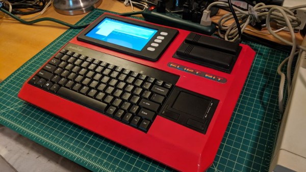
Granted the recent build by [lewisb42] still leans heavily on those common tropes, but at least there’s a clear lineage: his Raspberry Pi retro all-in-one is styled after a particularly rare bright red variant of the MSX that Sony released in Japan. Known as the HIT-BIT HB-101, some aficionados consider the circa-1984 machine to be the peak of MSX styling. Since getting his hands on a real one to retrofit wasn’t really an option, he had no choice but to attempt recreating some of the computer’s unique design elements from scratch.
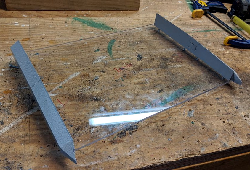
 The faceted sides were 3D printed in pieces, glued together, and then attached to a 1/4″ thick backplate made out of polycarbonate. For the “nose” piece under the keyboard, [lewisb42] actually used a piece of wood cut at the appropriate angles with a table saw. The top surface of the computer, which he calls the FLIPT-BIT, is actually made of individual pieces of foamed PVC sheet.
If all this sounds like a big jigsaw puzzle, that’s because it basically is. To smooth out the incongruous surfaces, he used a combination of wood putty, body filler, spot putty, and more time sanding then we’d care to think about. For the 3D printed surface details such as the screen bezel and faux cartridge slots, he used a coat of Smooth-On’s XTC-3D and yet more sanding. While [lewisb42] says the overall finish isn’t quite as good as he hoped, we think the overall look is fantastic considering the combination of construction techniques hiding under that glossy red paint job.
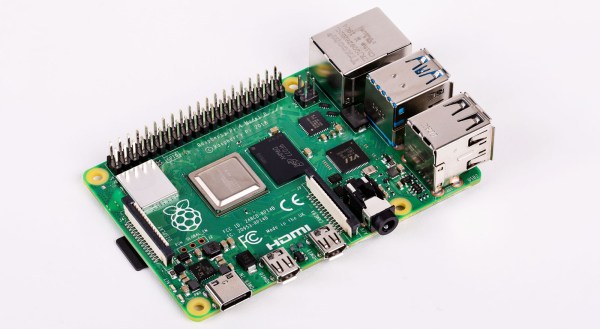
As for the electronics, there’s really no surprises there. The FLIPT-BIT uses a keyboard and touchpad from Perixx, a seven inch TFT display, and of course the Raspberry Pi 3. The display runs at 12 V so [lewisb42] used a combination of a generic laptop-style power supply and a 5 V step-down converter to keep everyone happy. While it doesn’t currently have a battery, it seems like there’s more than enough room inside the case to add one if he ever wants to go mobile.
If this build doesn’t properly scratch your Neuromancer itch, never fear. Just take a look at this decidedly less friendly-looking build that even includes a VR headset for properly jacking yourself into the matrix.