A Scientist Made An Artificial Black Hole In The Lab, And You Won’t Believe What Happened Next

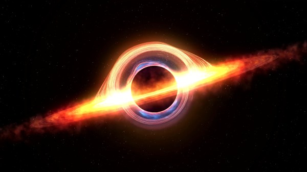
OK, that was a little click-baity, but then again, so was the announcement this week that a scientist had confirmed Hawking radiation with a lab-grown black hole. It sure got our attention, at least.

As it turns out, the truth is both less and more than meets the eye. The article above was eventually edited to better reflect the truth that, alas, we have not yet found a way to create objects so massive that even light cannot escape them. Instead, physicist [Jeff Steinhauer] and colleagues at the Technion-Israel Institute of Technology have developed an acoustic model of black holes, which is what was used to observe the equivalent of Hawking radiation for the first time. Hawking radiation is the theoretical exception to the rule that nothing makes it out of a black hole and would imply that black holes evaporate over time. The predicted radiation would be orders of magnitude weaker than the background radiation, though, making it all but impossible to detect.

That’s where [Steinhauer]’s sonic black holes come in. In these experiments, phonons, packets of mechanical vibrations that stand in for photons, are trapped in a fast-moving stream of fluid. The point in the stream where its speed straddles the local speed of sound is the equivalent to a real black hole’s event horizon; phonons inside that boundary can never escape. Except, of course, for the sonic equivalent of Hawking radiation, which the researchers found after 97,000 attempts.

When we first stumbled upon this story, we assumed a lab-grown black hole, even an acoustic analog, would take a CERN’s-worth of equipment to create. It turns out to be far simpler than that; [Steinhauer], in fact, built his black hole machine singlehandedly from relatively simple equipment. The experiments do require temperatures near absolute zero and a couple of powerful lasers, so it’s not exactly easy stuff; still, we can’t help but wonder if sonic black holes are within the reach of the DIY community. Paging [Ben Krasnow] and [Sam Zeloof], among others.

[Featured image credit: Nitzan Zohar, Office of the Spokesperson, Technion]

Sea Level: How Do We Measure Global Ocean Levels And Do Rising Oceans Change That Benchmark?

Every summer you go down the shore, but lately you’ve begun to notice that the beach seems narrower each time you visit. Is that the sea level rising, or is the sand just being swept away? Speaking of sea levels, you keep hearing that they rise higher every year — but how exactly is that measured? After all, you can’t exactly use a ruler. As it turns out, there are a number of clever systems in place that can accurately measure the global sea level down to less than an inch and a half.

Not only are waves always rippling across the ocean’s surface, but tides periodically roll in and out, making any single instantaneous measurement of sea level hopelessly inaccurate. Even if you plan to take hundreds or thousands of measurements over the course of weeks or months, taking the individual measurements is still difficult. Pick a nice, stable rock in the surf, mark a line on it, and return every hour for two weeks to hold a tape measure up to it. At best you’ll get within six inches on each reading, no matter what you’ll get wet, and at worst the rock will move and you’ll get a damp notebook full of useless numbers. So let’s take a look at how the pros do it.

Continue reading “Sea Level: How Do We Measure Global Ocean Levels And Do Rising Oceans Change That Benchmark?”

3D Printing 90° Overhangs With Non-Planar Slicing

When slicing a model for 3D printing, the part is divided into a stack of flat, 2D layers. But there’s an alternative in the form of non-planar slicing, where the layers can follow 3D curves. [Rene K. Mueller] took this a step further and successfully used non-planar slicing to print 90° overhangs on a normal Cartesian FDM printer.

Non-planar layers have been around for a while, but were generally limited to creating smooth curves without layer lines. The idea of using the technique for overhangs had been floating around in [Rene]’s head for a while, and he was spurred to action after seeing the rotating tilted nozzle printer featured here on Hackaday. The idea is only to have the outer edge of each layer overhang, by making each layer slope downward toward the overhang. [Rene] programmed a conic slicer algorithm for this purpose, which splits the model into dome-shaped layers, like an onion.

He did a lot of testing and documented the results in detail. Conical slices were compared with tilted slices, which are also used for belt 3D printers. Both have some geometric limitations. Tilted slices can only print the overhang in one direction, but conical slices can do this in all directions, allowing it to create a mushroom-like shape without any support. The limitation is that it can only print inward or outward from a central point. More complex geometry must be segmented, and each sub-volume sliced separately. The slicing angle is also limited by the shape of the print head, to avoid it crashing into the print.

We think this technique has a lot of potential for widespread use, especially since it is compatible with most existing FDM printers. It is still a work in progress, but support has already been added for Slic3r and Prusa Slicer. We look forward to seeing how it develops and gets adopted.

AVR Configurable Custom Logic As A Frequency Divider At 4x Chip’s Clock Speed

What a time to be alive when you can find inexpensive microcontrollers that come with programmable(ish) logic that can operate independently of the system clock. [David Johnson-Davies] recently built a proof of concept using the Configurable Custom Logic (CCL) that is available in some of the newer AVR microcontroller designs. It’s a simple implementation, a set of frequency dividers that blink three LEDs with up to a 90 MHz input signal. But the simplicity is the reason to love his write-up — you can wrap your head around it right away.

There are four lookup table (LUTs) used to form the frequency divider. Think of these like a NAND or XOR gate, but you get to decide how the output truth tables will perform. The output is fed into a sequencer which can be configured as a D/JK flip-flop or a D/RS latch, plus you can specify the signal edge, and of course define the clock source. An interesting trick here is to hold the G input of both D flip-flops high by feeding them LUTs set to all ones. Note that the output of the first divider (PA3) is feeding the external input (PD2) of the second divider.

While the CCL is configured using the C code you flash to the microcontroller, it’s a hardware peripheral capable of operating independent of the chip’s system clock. The AVR128DA28 that’s used here tops out at 24 MHz (double that if you use the PLL) but [David] got reliable results from his clock divider feeding a signal as high as 90 MHz to the input pin. Of course you have the option of feeding internal clock signals to the CCL, but that wouldn’t seem nearly as interesting here. For the demo, [David] is actually toggling an IO pin which is connected to PA2 as the external input for the logic. Make sure you click through to his write-up linked above as he does an excellent job of walking through the sample code (just a couple-dozen lines to set this all up). Here’s the datasheet for this chip (PDF, page 447 for pertinent registers) and for a deeper dive the appnote on CCL (PDF).

So what is this all good for? We already saw an answer to that question back in January when [SM6VFZ] used the CCL peripheral to build a software-defined switch-mode converter. How awesome is that?