Simple PCB Repairs Keep Old Vehicle Out Of The Crusher

For those of us devoted to keeping an older vehicle on the road, the struggle is real. We know that at some point, a part will go bad and we’ll learn that it’s no longer available from the dealer or in the aftermarket, at least at a reasonable cost. We might get lucky and find a replacement at the boneyard, but if not — well, it was nice knowing ya, faithful chariot.

It doesn’t have to be that way, though, at least if the wonky part is one of the many computer modules found in most cars made in the last few decades. Sometimes they can be repaired, as with this engine control module from a Ford F350 pickup. Admittedly, [jeffescortlx] got pretty lucky with this module, which with its trio of obviously defective electrolytics practically diagnosed itself. He also had the advantage of the module’s mid-90s technology, which still relied heavily on through-hole parts, making the repair easier.

Unfortunately, his luck stopped there, as the caps had released the schmoo and corroded quite a few traces on the PCB. Complicating the repair was the conformal coating on everything, a common problem on any electronics used in rough environments. It took a bit of probing and poking to locate all the open traces, which included a mystery trace far away from any of the leaky caps. Magnet wire was used to repair the damaged traces, the caps were replaced with new ones, and everything got a fresh coat of brush-on conformal coating.

Simple though they may be, we really enjoy these successful vehicle module repairs because they give us hope that when the day eventually comes, we’ll stand a chance of being able to perform some repair heroics. And it’s nice to know that something as simple as fixing a dead dashboard cluster can keep a car out of the crusher.

Continue reading “Simple PCB Repairs Keep Old Vehicle Out Of The Crusher”

PCB Repair Is A Sticky Proposition

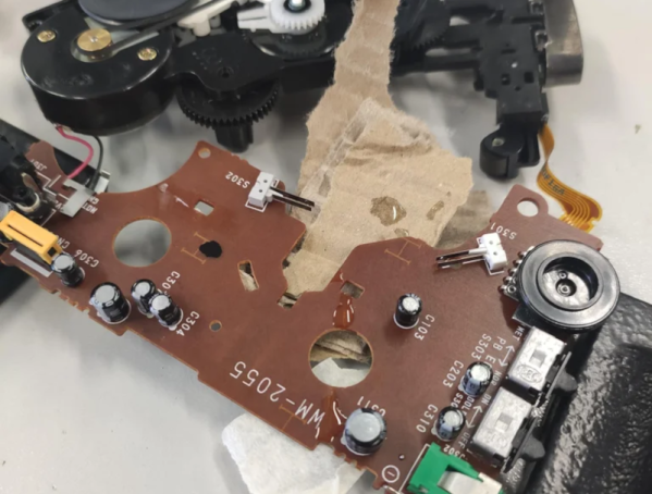
What do you do when a PCB is cracked or even broken in two? [MH987] has a plan: superglue the board back and then bridge the traces with solder, solder paste, or wire. The exact method, of course, depends on the extent of the damage.

We’ve had some success with similar techniques, and, honestly, for single-sided boards, we would be tempted to add a thin backer behind the crack. We’ve also used conductive paint to repair traces, but it’s good to have having as many tricks as possible because you never know what will work best for a particular repair. The post mentions that this is easier to do on a single-sided board, but it is certainly possible to do on a two-layer board.

The example repair is a Walkman which — if you are a youngster — was a portable music player that takes cassette tapes. These haven’t been made since 2010, so it is important to repair what you have.

If you can’t repair your Walkman, you could build an updated version. If your board is seriously damaged, you might get hope from this more extreme repair.

Five Ways To Repair Broken PCB Traces

When everything used wires, it was easy to splice them or replace them. Not so much with PC boards, but everyone has their favorite method for repairing a broken trace. [Mr. SolderFix] has his five favorite ways, as you can see in the video below.

Of course, before you can repair a trace, you probably have to expose it since most boards have solder mask now. Unless you plan to shut the trace at both ends, exposing the actual trace is probably the first step.

Continue reading “Five Ways To Repair Broken PCB Traces”

PCB Solder Pad Repair & Cleanup

What do you do when your motherboard is covered in electrolytic grime, has damaged pads and traces that are falling apart? You call [RetroGameModz] to work their magic with epoxy and solder.

While this video is a bit old, involved repair videos never go out of style. What makes this video really special is that it breaks from the common trend of “watch me solder in silence” (or it’s close cousin, “watch me solder to loud music”). Instead, [RetroGameModz] walks you through what they’re doing, step by step in their repair of a motherboard. And boy do they have their work cut out for them: the motherboard they’re working on has definitely seen better days. Specifically, it was better before corrosion from a leaking electrolytic capacitor and the well-meaning touch of its owner.

After a quick review of the damage, all of the components are removed from the battle zone. Then the cleaning begins, taking special precautions not to rip pads up. After everything’s cleaned up, things get really interesting. [RetroGameModz] starts to make their own pads from raw copper using the old pads as templates to replace the missing ones on the motherboard. After a bit of epoxy, it’s hard to tell that the pads were handmade, they fit in so well.

This epoxy trick is also used to deal with some heavily damaged traces, cool! During this repair, [RetroGameModz] used an epoxy that is heat resistant up to 315°C for 60 seconds. If you ever find any kind of epoxy on the market that is specified to be heat resistant up to more than 315°C, [RetroGameModz] would be quite happy if you could leave some info in the comment section, as they’ve found high-temperature epoxies quite difficult to source.

This goes to show that some repairs really should be done by professionals. [RetroGameModz] surely agrees, stating that “If you are not a repair technician and your motherboard has stopped working, it would be in the best of your own interest not to attempt a repair that you really cannot handle.” Good advice. But, we can never resist trying to fix things ourselves before handing things off to the more experienced. Call it a vice, or a virtue; we’ll call it fun.

What do you think? Are there some repairs you rely on technicians for? Or do you fix everything yourself? Let us know in the comments.

Continue reading “PCB Solder Pad Repair & Cleanup”

Extreme Repair Of A Burnt PCB

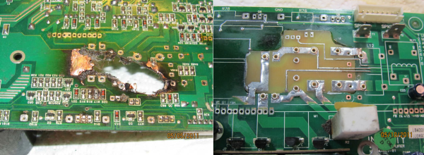
[xsdb] had a real problem. His JBL L8400P 600 watt subwoofer went up in flames – literally. Four of the large capacitors on the board had bulged and leaked. The electrolyte then caused a short in the mains AC section of the board, resulting in a flare up. Thankfully the flames were contained to the amplifier board. [xsdb’s] house, possessions, and subwoofer enclosure were all safe. The amplifier board however, had seen better days. Most of us would have cut our losses and bought a new setup. Not [xsdb] he took on the most extreme PCB repair we’ve seen in a long time.

After removing the offending caps and a few other components, [xsdb] got a good look at the damage. the PCB was burned through. Charred PCB is conductive, so anything black had to be cut out. The result was a rather large hole in the middle of an otherwise serviceable board. [xsdb] had the service manual for the JBL sub. Amazingly, the manual included a board layout with traces. Some careful Photoshop work resulted in an image of the section of PCB to be repaired. [Xsdb] used this image to etch a small patch board.

The amplifier and patch were milled and sanded to match up nearly perfectly. Incredibly, all the traces aligned. [Xdsb] soldered the traces across the join with small sections of wire and solder wick. After soldering in some new high quality capacitors, the amplifier was back in action!

If you’re a big fan of burned PCB’s, check out Hackaday Prize Judge Dave Jones latest EEVblog video, where he works on a Ness home alarm panel with a similarly cooked section of FR4.

[Thanks for the link JohnS_AZ!]

Repairing The Questionable £25,000 Tom Evans Audiophile Pre-Amp

One of the power supply boards in the Tom Evans Mastergroove SR MkIII preamplifier. (Credit: Mend it Mark, YouTube)

It’s not much of a secret that in the world of ‘audiophile gear’ there is a lot of snake oil and deception, including many products that are at best of questionable value. The Tom Evans Mastergroove SR mkIII preamplifier is one example of this, as [Mark] from the Mend it Mark YouTube channel found in a recent video when he got one to repair which the manufacturer claimed ‘could not be fixed’. This marvel of audio engineering provides amplification for record players, for the low-low price of only twenty-five thousand quid, or about 29.000 US bucks. So what’s inside one of these expensive marvels?

Claiming to be a high-end unit, with only ten units produced per year, you’d expect a gold-plated PCB with excellent noise isolation. The unit does come with an absolutely massive external power supply that dwarfs the preamplifier itself, but the real surprise came after opening up the unit itself to take a peek at the damage, some of which was caused by transport.

As it turns out, the inside of the preamplifier consists out of four stacks of rather cheap, home-made looking boards with what looks like improvised RF shielding in the form of bare PCBs and filed-off markings on many parts. In between the rat’s nest of wiring running everywhere, [Mark] had to trace the broken channel’s wiring, creating a full repair manual in the process. Along the way one of the opamp boards was found to be defective, courtesy of a single shorted tantalum capacitor.

With the tantalum capacitor replaced, [Mark] had repaired the unit, but even though the preamplifier isn’t terribly designed, the illusion of its price tag has been shattered worse than the contents of a parcel kicked across the parking lot by the Royal Mail.

Thanks to [Jim] for the tip.

Continue reading “Repairing The Questionable £25,000 Tom Evans Audiophile Pre-Amp”

Power Supply PCB Redesign

We’ve often heard you should do everything twice. The first time is to learn what you need to do, and the second time is to do it right. We bet [Ian Carey] would agree after taking his old linear power supply PCB and changing it to a switching regulator design. You can see more about the project in the video below.

The first power-up revealed a problem with the 3.3V output. We’ve often thought it is harder to troubleshoot a new design than it is to repair something that is known to have worked at one time.

Continue reading “Power Supply PCB Redesign”