Homemade VNA Delivers High-Frequency Performance On A Budget

With vector network analyzers, the commercial offerings seem to come in two flavors: relatively inexpensive but limited capabilities, and full-featured but scary expensive. There doesn’t seem to be much middle ground, especially if you want something that performs well in the microwave bands.

Unless, of course, you build your own vector network analyzer (VNA). That’s what [Henrik Forsten] did, and we’ve got to say we’re even more impressed by the results than we were with his earlier effort. That version was not without its problems, and fixing them was very much on the list of goals for this build. Keeping the build affordable was also key, which resulted in some design compromises while still meeting [Henrik]’s measurement requirements.

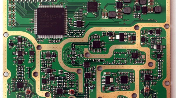
The Bill of Materials includes dual-channel broadband RF mixer chips, high-speed 12-bit ADCs, and a fast FPGA to handle the torrent of data and run the digital signal processing functions. The custom six-layer PCB is on the large side and includes large cutouts for the directional couplers, which use short lengths of stripped coaxial cable lined with ferrite rings. To properly isolate signals between stages, [Henrik] sandwiched the PCB between a two-piece aluminum enclosure. Wisely, he printed a prototype enclosure and lined it with aluminum foil to test for fit and function before committing to milling the final version. He did note some leakage around the SMA connectors, but a few RF gaskets made from scraps of foil and solder braid did the trick.

This is a pretty slick build, especially considering he managed to keep the price tag at a very reasonable $300. It’s more expensive than the popular NanoVNA or its clones, but it seems like quite a bargain considering its capabilities.

Fixing An Unpleasant SD Card Slot Issue In A NanoVNA

SD cards & the much smaller microSD cards are found on many devices, with the card often accessible from outside the enclosure. Unfortunately there’s a solid chance that especially small microSD cards will find their way past the microSD card reader slot and into the enclosure. This is what happened to [Rob] of the SevenFortyOne Radios and Repairs channel on YouTube with a NanoVNA unit. While shaking the unit, you can clearly hear the microSD card rattling inside, courtesy of the rather large gap above the card slot.

After a quick teardown and extracting the lost microSD card, the solution to prevent this is a simple bit of foam stuck on top of the microSD card slot, so that the too large opening in the enclosure is now fully blocked. It’s clearly a bit of a design fail in this particular NanoVNA unit, worsened by the tiny size of the card and having to use a fingernail to push the card into the slot as it’s so far inside the enclosure.

While [Rob] seems to blame himself for this event, we’d chalk it mostly up to poor design. It’s an issue that’s seen with certain SBC enclosures and various gadgets too, where losing a microSD card is pretty much a matter of time, and hugely fiddly at the best of times. That said, what is your preferred way of handling microSD card insertion & removal in devices like these?

Continue reading “Fixing An Unpleasant SD Card Slot Issue In A NanoVNA”

VNAs And Crystals

Oscillators may use crystals as precise tuned circuits. If you have a vector network analyzer (VNA) — or even some basic test equipment — you can use it to learn the parameters of a crystal. [All Electronics Channel] has the details, and you can see how in the video below.

There was a time when a VNA was an exotic piece of gear, but these days they are relatively common. Crystal parameters are important because crystals have a series resonance and a parallel resonance and they are not at the same frequency. You also may need to know how much loading capacitance you have to supply to get the crystal at the right frequency.

Sometimes, you want to pull the crystal frequency, and the parameters will help you figure that out, too. It can also help if you have a crystal specified as series in a parallel-mode oscillator or vice versa.

If you don’t have a VNA, you can use a tracking signal generator, as [Grégory] shows towards the middle of the video. The quality of a tuned circuit depends on the Q factor, and crystals have a very high Q factor.

We did something similar in 2018. The other way to pull a crystal frequency is a bit extreme.

Continue reading “VNAs And Crystals”

A NanoVNA As A Dip Meter

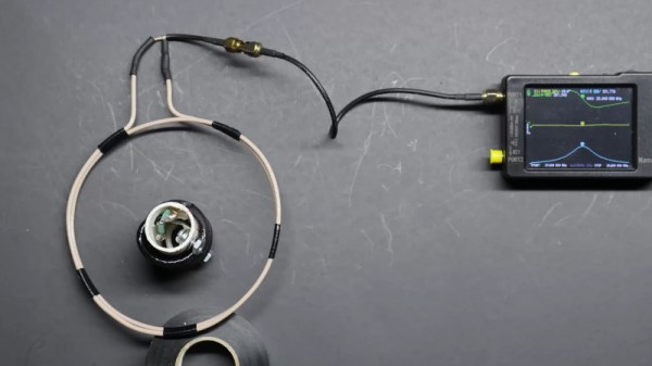
A staple of the radio amateur’s arsenal of test equipment in previous decades was the dip meter. This was a variable frequency oscillator whose coil would be placed near the circuit to be tested, and which would show an abrupt current dip on a moving coil meter when its frequency matched the resonant frequency of what it was testing. For some reason the extremely useful devices seem hard to come by in 2024, so [Rick’s Ham Shack] has come along with a guide to using a nanoVNA in their place.

It’s a simple enough technique, indeed it’s a basic part of using these instruments, with a large sensor coil connected to the output port and a frequency sweep set up on the VNA. The reactance graph then shows any resonant peaks it finds in the frequency range, something easily demonstrated in the video below the break by putting a 20 meter (14 MHz) trap in the coil and seeing an immediate clear peak.

For many readers this will not be news, but for those who’ve not used a VNA before it’s a quick and easy demo of an immediate use for these extremely versatile instruments. For those of us who received our callsigns long ago it’s nothing short of miraculous that a functional VNA can be picked up at such a reasonable price, and we’d go as far as to suggest that non radio amateurs might find one useful, too. Read our review, if you’re interested.

Continue reading “A NanoVNA As A Dip Meter”

Calibrating A VNA The Proper Way

Those of us who have bought cheap TinyVNA devices for our RF experimentation will be used to the calibration procedure involving short-circuit, 50 Ω, and open terminations, followed by a direct connection between ports. We do this with a kit of parts supplied with the device, and it makes it ready for our measurements. What we may not fully appreciate at the level of owning such a basic instrument though, is that the calibration process for much higher-quality instruments requires parts made to a much higher specification than the cheap ones from our TinyVNA. Building a set of these high-quality parts is a path that [James Wilson] has taken, and in doing so he presents a fascinating discussion of VNA calibration and the construction of standard RF transmission line components.

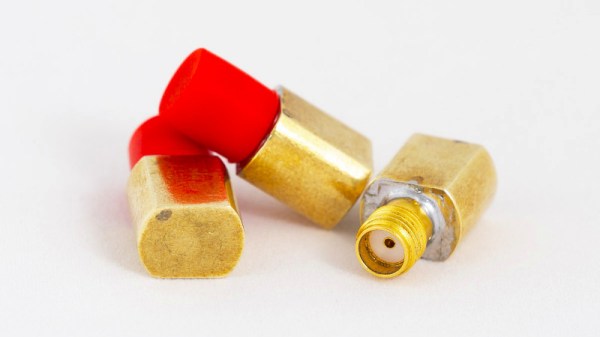
We particularly like the way that after constructing his short, load and open circuit terminations using high-quality SMA sockets, he put a custom brass fitting 3D printed by Shapeways on the end of each to make them easier to handle while preserving their RF integrity. If we’d bought a set of terminations looking like these ones as commercial products we would be happy with their quality, but the real test lay in their performance. Thanks to a friend he was able to get them tested on instruments with much heftier price tags, and found them to be not far short of the simulation and certainly acceptable within his 3 GHz range.

Curious about VNAs at the affordable end of the spectrum? We took a look at the TinyVNA, which while it is something of a toy is still good enough for lower frequency measurements.

LibreVNA Is A Quality Open Hardware Vector Network Analyser

There was a time when a Vector Network Analyser or VNA was the type of instrument that cost as much as a very fancy car or even a small house. The advent of commodity semiconductors that perform at high RF frequencies coupled with microcontrollers powerful enough to handle the data acquisition and processing might not yet have put those high-perfomance instruments within reach, but at our end of the market it’s opened the possibilities for some useful yet affordable devices. A fresh contender comes from [Jankae], whose LibreVNA tops out at 6 GHz and shows some significant attention to design detail that puts it above some of the budget offerings.

At its heart is the versatile Si5351 multi-way clock generator, accompanied by a pair of MAX2871 phase-locked-loop chips for the higher frequency local oscillators. A switched bank of low-pass filters take care of local oscillator harmonics, and in the receive chain there are ADL5081 mixers feeding a dual conversion IF running at 70 MHz and then 300 kHz. Finally the ADCs are Microchip’s MCP3313, and all is kept in sync by an FPGA and an STM32G431 microcontroller. The main data proccessing is offloaded to a host computer, with a software package and GUI able to be compiled on Windows, Linux, and OSX.

The PCB shows the attention to detail, not least in the power supply arrangements, with every major component receiving its own regulator to ensure no RF makes it down the power rails. It’s clear that a properly made LibreVNA won’t be as cheap as some of its rivals, but we think the corresponding performance hike would make the extra cost worthwhile.

If VNAs are new to you, we covered an introduction from [W2AEW] a while back.

Learning About VNAs

We live in a good time to be an electronics geek. It used to be only the richest or shrewdest among us had a really good oscilloscope, while these days it is entirely feasible to have a scope that would have cost a fortune a few decades ago, a logic analyzer, arbitrary waveform generator, and what would have once been a supercomputer and still not be in debt. One of the cooler pieces of gear for people working on RF electronics is a vector network analyzer (VNA) which used to be exotic, but now can be bought for very little. But what do you do with it? [W2AEW] has the answer.

We always look forward to a video from [W2AEW]. Even if we know about the subject he covers, we usually pick up something new or interesting. Like all of his videos, this one is intensely practical. Not a lot of drawing but plenty of scope shots and experimenting.

Continue reading “Learning About VNAs”