Ham Reviews MiniVNA

[KB9RLW] wanted to build a vector network analyzer (VNA), but then realized he could buy a ready-made one without nearly the cost it would have been only a few years ago. The network in this case, by the way, is an electrical network, not a computer network. You can use a VNA to characterize components, circuits, antennas, and even feed lines at different frequencies. The miniVNA Pro is economical and can exercise circuits from 1 MHz to 3 GHz. You can see the review in the video below.

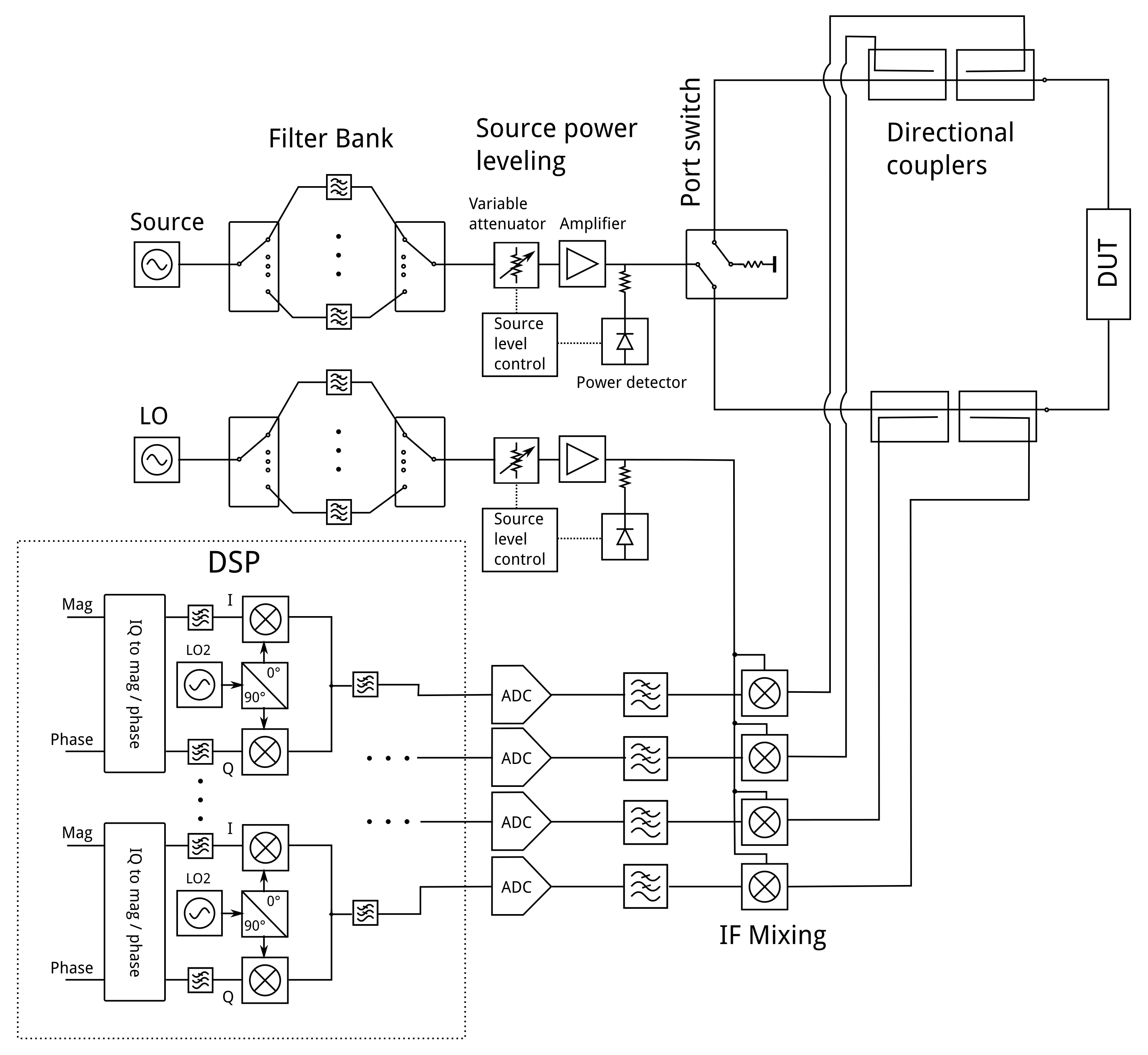
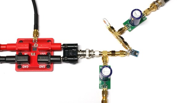
There are a few ways to actually create a VNA, but in concept, it is a sweep generator, a detector, and a means to plot the response at each frequency in the sweep. So you’d expect, for example, a resonant frequency to show a peak at resonance and a band reject filter to show a low point.

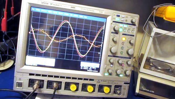
One of the things interesting about the device is that it uses Java software. That means it doesn’t care much what platform you want to use. The software can show two different plots at once, so [Kevin] hooks it to his 20 meter antenna and shows how it can plot the SWR and impedance around the frequency of interest.

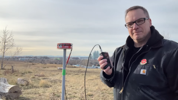
The instrument can be USB powered with the same cable you use to connect the PC. However, it also has an internal rechargeable battery. That battery charges on USB and can operate the device with Bluetooth. We can imagine that being handy when you want to climb up a tower and connect it directly to an antenna as long as you stay in Bluetooth range of the PC. There’s also a phone app, so you can go that route, if you prefer and [Kevin] shows the device working with Android. Of course, you could probably rig a Raspberry Pi on your belt and then use WiFi to let someone on the ground remote desktop in to run measurements. A lot of possibilities.

If you want to roll your own, that’s possible, of course. If you want to get by a bit cheaper, there are less expensive options.

Continue reading “Ham Reviews MiniVNA”

A VNA On A 200 Euro Budget

If you were to ask someone who works with RF a lot and isn’t lucky enough to do it for a commercial entity with deep pockets what their test instrument of desire would be, the chances are their response would mention a vector network analyser. A VNA is an instrument that measures the S-parameters of an RF circuit, that rather useful set of things to know whose maths in those lectures as an electronic engineering student are something of a painful memory for some of us.

The reason your RF engineer respondent won’t have a VNA on their bench already will be fairly straightforward. VNAs are eye-wateringly expensive. Second-hand ones are in the multi-thousands, new ones can require the keys to Fort Knox. All this is no obstacle to [Henrik Forstén] though, he’s built himself a 30MHz to 6 GHz VNA on the cheap, with the astoundingly low budget of 200 Euros.

The operation of a VNA

On paper, the operation of a VNA is surprisingly simple. RF at a known power level is passed through the device under test into a load, and the forward and reverse RF is sampled on both its input and output with a set of directional couplers. Each of the four couplers feeds what amounts to an SDR, and the resulting samples are processed by a computer. His write-up contains a full run-down of each section of the circuit, and is an interesting primer on the operation of a VNA,

[Henrik] admits that his VNA isn’t as accurate an instrument as its commercial cousins, but for his tiny budget the quality of his work is evident in that it is a functional VNA. He could have a batch of these assembled and he’d find a willing queue of buyers even after taking into account the work he’s put in with his pricing.

[Henrik]’s work has appeared on these pages several times before, and every time he has delivered something special. We’ve seen his radar systems, home-made horn antennas, and a very well-executed ARM single board computer. This guy is one to watch.

Thanks [theEngineer] for the tip.

Reverse Engineering The Quansheng Hardware

In the world of cheap amateur radio transceivers, the Quansheng UV-K5 can’t be beaten for hackability. But pretty much every hack we’ve seen so far focuses on the firmware. What about the hardware?

To answer that question, [mentalDetector] enlisted the help of a few compatriots and vivisected a UV-K5 to find out what makes it tick. The result is a complete hardware description of the radio, including schematics, PCB design files, and 3D renders. The radio was a malfunctioning unit that was donated by collaborator [Manuel], who desoldered all the components and measured which ones he could to determine specific values. The parts that resisted his investigations got bundled up along with the stripped PCB to [mentalDetector], who used a NanoVNA to characterize them as well as possible. Documentation was up to collaborator [Ludwich], who also made tweaks to the schematic as it developed.

PCB reverse engineering was pretty intense. The front and back of the PCB — rev 1.4, for those playing along at home — were carefully photographed before getting the sandpaper treatment to reveal the inner two layers. The result was a series of high-resolution photos that were aligned to show which traces connected to which components or vias, which led to the finished schematics. There are still a few unknown components, The schematic has a few components crossed out, mostly capacitors by the look of it, representing unpopulated pads on the PCB.

Hats off to the team for the work here, which should make hardware hacks on the radio much easier. We’re looking forward to what’ll come from this effort. If you want to check out some of the firmware exploits that have already been accomplished on this radio, check out the Trojan Pong upgrade, or the possibilities of band expansion. We’ve also seen a mixed hardware-firmware upgrade that really shines.

Understand Your Tools: Finger Exercises

A dip meter is basically a coil of wire that, when you excite it, you can use to tell if something inside that coil is resonating along. This lets you measure unknown radio circuits to figure out their resonant frequency, for instance. This week, we featured a clever way to make a dip meter with a nanoVNA, which is an odd hack simply because a dip meter used to be a common spare-parts DIY device, while a vector network analyzer used to cost more than a house.

Times have changed, and for the better. Nowadays, any radio amateur can pick up a VNA for less than the cost of all but the cheesiest of walkie talkies, putting formerly exotic test equipment in the hands of untrained mortals. But what good is a fancy-pants tool if you don’t know how to use it? Our own Jenny List faced exactly this problem when she picked up a nanoVNA, and her first steps are worth following along with if you find yourself in her shoes.

All of this reminded me of an excellent series by Mike Szczys, “Scope Noob”, where he chronicled his forays into learning how to use an oscilloscope by running all of the basic functions by working through a bunch of test measurements that he already knew the answer to.

It strikes me that we could use something like this for nearly every piece of measuring equipment. Something more than just an instruction manual that walks you through what all the dials do. Something that takes you through a bunch of example projects and shows you how to use the tool in question through a handful of projects. Because these days, access to many formerly exotic pieces of measuring gear has enabled many folks to have gear they never would have had before – and all that’s missing is knowing how to drive them.

The line injector shown characterising the PSRR of an AMS1117 regulator, with a bunch of stuff connected to it through SMA jacks

A Simple Line Injector Shows You The Wonderful World Of PSRR

[limpkin] writes us to show a line injector they’ve designed. The principle is simple — if you want to measure how much PSU noise any of your electronic devices let through, known as PSRR (Power Supply Rejection Ratio), you can induce PSU noise with this board, and then measure noise on your device’s output. The board is likewise simple. A few connectors, resistors, and caps, and a single N-FET!

You do need a VNA, but once you have that, you get a chance to peek into an entire world of insights. Does that 1117 LDO actually filter out noise better than a buck regulator? Is it enough to use a Pi filter for that STM32’s ADC rail, and do the actual parts you’re using actually help with that task? How much noise does your device actually let through in the real world, after being assembled with the specific components you’ve picked? [limpkin] shows us a whole bunch of examples – putting regulators, filters and amplifiers to the test, and showing us how there’s more than meets the eye.

Everything is open source, with full files available on the blog. And, if you want it pre-assembled, tested and equipped with the CNC-milled case, you can get it on Tindie or Lektronz! Of course, even without a tool like this, you can still get good filter designs done with help of computer-aided modelling.

We thank [alfonso] for sharing this with us!

Simulate A Better Termination

If you are making certain precision measurements, you know you need to terminate the connections with the right impedance, normally 50 ohms. Proper termination minimizes reflections on the line which can disturb measurements. Some instruments already have 50 ohm terminations, at least optionally. If not, you usually use little connector shells with the right resistor inside. [Joe Smith] decided to see if he could improve on the normal terminations using circuit simulation techniques. You can see a video of the work below.

In the process of testing, he also needs a resistive splitter, and, just like with the terminators, he shows you what’s going on inside. It was easy to compare since he had a scope that could independently set channels to have a 50-ohm termination or a 1 megaohm termination.

Continue reading “Simulate A Better Termination”

A Canned Ham Ham Antenna

If you’d have asked us for odds on whether you could successfully turn a canned ham into an amateur radio antenna, we’d have declined the offer. Now, having seen [Ben Eadie (VE6SFX)]’s “hamtenna” project, we’d look at just about any “Will it antenna?” project with a lot less skepticism than before.

To be painfully and somewhat unnecessarily clear about [Ben]’s antenna, the meat-like product itself is not in the BOM for this build, although he did use it as sustenance. Rather, it was the emptied and cleaned metal can that was the chief component of the build, along with a few 3D printed standoffs and the usual feedline and connectors. This is a slot antenna, a design [Ben] recently experimented with by applying copper foil tape to his car’s sunroof. This time around, the slot was formed by separating the top and bottom of the can using the standoffs and electrically connecting them with a strip of copper tape.

Connected to a stub of coax and a BNC connector, a quick scan with a NanoVNA showed a fantastic 1.26:1 SWR in the center of the 70-cm ham band, and a nearly flat response all the way across the band. Results may vary depending on the size of canned ham you sacrifice for this project; [Ben]’s can measured just about 35 cm around, a happy half-wavelength coincidence. And it actually worked in field tests — he was able to hit a local repeater and got good signal reports. All that and a sandwich? Not too shabby.

Continue reading “A Canned Ham Ham Antenna”