Over on Hackaday.IO our hacker [bornach] has his entry into the Component Abuse Challenge: Inductors are Wireless Power Sources.
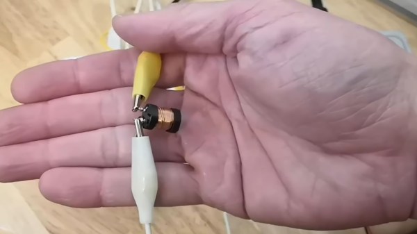
 Some time back [bornach] was gifted a Qi wireless charging base station but didn’t own any compatible devices. He had a dig around in his junk box for inductors to attempt coupling to the wireless charger and lucked out with an inductor salvaged from his old inkjet printer.
There are actually open standards, known as the Qi standards, for how to negotiate power from a Qi device. But [bornach] ignored all of that. Instead he leveraged the fact that the Qi base station will periodically send out a “ping” containing a small measure of power to let compatible devices know that it’s available for negotiation. It is the energy in this “ping” that power’s [bornach]’s circuit!
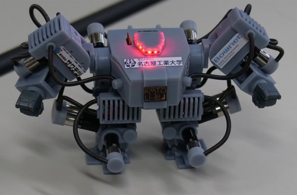
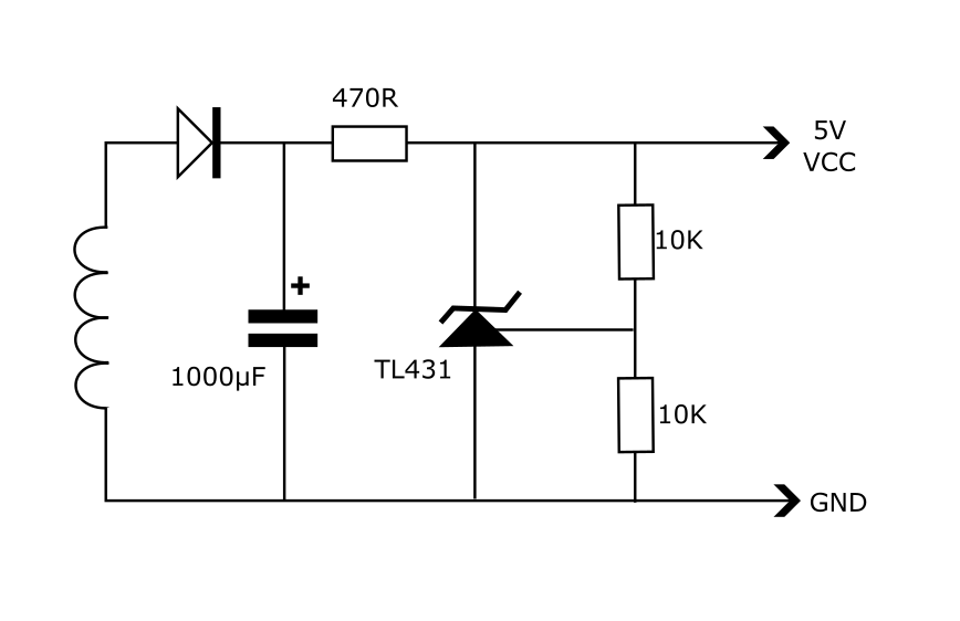
In [bornach]’s circuit a TL431 provides a regulated five volt supply which can be used to drive a microcontroller and a charliplexed array of ten LEDs. Pretty nifty stuff. If you’re new to wireless charging you might like to know How Wireless Charging Works And Why It’s Terrible. Continue reading “2025 Component Abuse Challenge: Using Inductors To Steal Power From Qi Wireless Charging Base Station”