DIY Mini-Drill Would Make Mad Max Proud

mini-drill

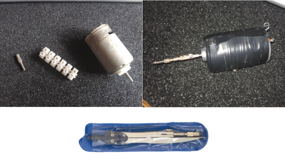
That’s not a prison tattoo gun up there, it’s [Szabolcs] DIY mini drill. Hackaday has been on a bit of a DIY tool kick lately – with improvised saws, grinders, and grinders converted to saws, among other things. We haven’t had any DIY drills yet, though. [Szabolcs] needed a drill for his home-made printed circuit boards. Usually a Dremel or similar rotary tool is pressed into service for drilling PCBs. However, for some reason he didn’t have access to one. [Szabolcs] called upon his inner MacGyver and built a drill from parts he had on hand.

Every drill needs a chuck, or at least a collet holder. This drill’s chuck is sourced from a drafting compass. Long ago in the dark ages before CAD, mechanical drawings were manually drawn up. Companies employed entire drafting departments to draw designs, blueprints, and schematics. These draftsmen used the compass to create accurate circles and arcs. [Szabolcs] re-used the lead holder from the compass as a chuck for his drill. A 540 or 550 brushed sealed endbell can motor, common to the R/C cars spins the drill up. We originally thought [Szabolcs] used an Erector or Meccano set piece as a shaft coupling. The truth is it’s the internals of a Euro style terminal strip. A small tactile button is used to activate the motor. Some electrical tape wrapped around the motor holds the button in place. The tape also makes sure that the user isn’t cut by the sheet metal field ring wrapped around the can. Power for the system can come from just about anywhere, though [Szabolcs] says he uses the 12v rail of an old ATX power supply.
Temperature Controller Gets Open Source Firmware Upgrade

stc1000

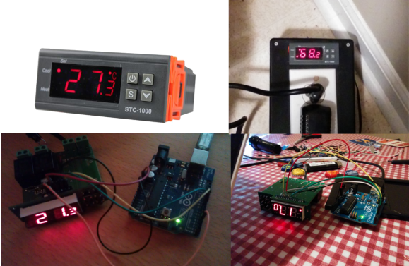
Beer lovers rejoice! [Mats] has reverse engineered a temperature controller and written new open source firmware for it. This effectively gives all us homebrewers a low cost, open source software driven controller. The STC-1000 is a cheap (under $20 USD) temperature controller mass-produced in the far east. The controllers do work, but have several limitations. The programming options are somewhat limited to basic set points for heat and cool. The controller also is only programmed for temperature display in Celsius, which is a bit of an annoyance for those of us who think in Fahrenheit. Under the hood, the STC-1000 utilizes a Microchip PIC16F1828 microcontroller. Unfortunately the PIC’s protection bits were set, so the original code would have been extremely difficult to extract. Not a problem, as [Mats] reverse engineered the hardware and wrote his own firmware. A 10k NTC thermister acts as the temperature probe. The probe is read by the PIC’s ADC. These probes are not very linear, so a look up table is used to convert from volts to degrees Celsius or Fahrenheit.

[Mats] new firmware allows for up to 6 profiles. Each profile has up to 10 set points and a time duration to hold each of the set points. Hysteresis and temperature offset values are also programmable via the front panel. PIC software is often written in C using Microchip’s MPLAB tool chain, and programmed with the PICkit 3 In Circuit Serial Programming (ICSP) tool. [Mats] decided to buck the system and wrote his C code using Small Device C Compiler. To keep things simple for homebrewers who may not have Microchip tools, [Mats] used an Arduino Uno for flashing duties. Thankfully the unholy matrimony of a PIC and an AVR has not yet caused a rift in time and space. The firmware is still very much in the beta stage, so if you want to help out, join the discussion on the homebrew talk forum. If you see [Mats] tell him we owe him a Haduino which he can use to almost open his beer.

[Thanks for the tip Parker!]

Panning GoPro Mount Catches Bad Drivers On Video

gopro-mount

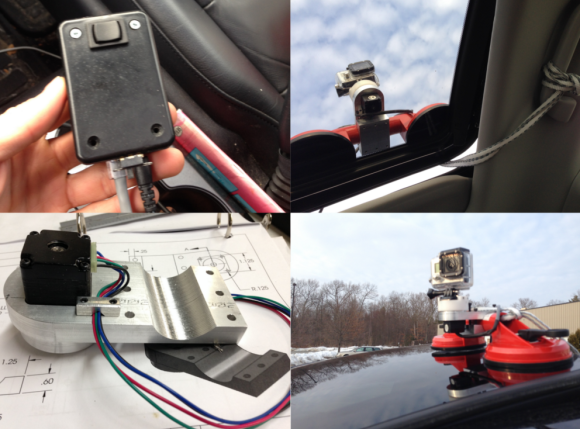
[Chris] must live in a neighborhood with a lot of bad drivers. He built this motorized panning GoPro mount so he can record and share his neighbors’ mobile misadventures with the world. He started with a custom machined aluminum frame. The frame clips onto a suction cup mount grab bar. The stock GoPro mount sits on a machined HDPE puck, which is rotated by a NEMA 11 stepper motor. [Chris] used a Pololu A4988 stepper motor driver to handle the coils. Initially he used an Arduino to generate pulses for the stepper driver. A true Hackaday fan though, he decided that an Arduino was overkill, and broke out a 555 timer. A DPDT switch powers up the 555 and controls the stepper driver’s direction input. The electronics all fit neatly in a small project box which doubles as a hand controller.

While setting up for a test drive [Chris] found that he could only lock down one suction cup on his car’s curved sunroof. Considering the light weight of the GoPro, one suction cup is probably enough. Just to be safe, [Chris] added a rope leash down through the sunroof.

We think the stepper motor was a good choice for this project. Since the motor is direct drive, there are no gears to strip. The stepper’s holding torque also keeps the camera pointed in the right direction at highway speeds. With no wires directly connecting the GoPro to the car, [Chris] can spin the camera 360 degrees without worrying about tangles. Verifying the camera’s direction is just a matter of looking up through the car’s sunroof. Click past the break to see [Chris’s] camera mount in action. 

Continue reading “Panning GoPro Mount Catches Bad Drivers On Video” →

Build Your Own Elektrosluch 2 And Save €45

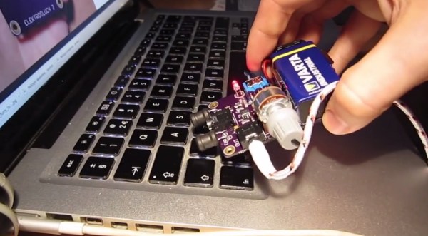
[Jonas] over at LOM Instruments is running an Indiegogo campaign for his newest creation, Elektrosluch 2. Like it’s predecessor, Elektrosluch 2 is a means to listen to the electromagnetic sounds of the world around you. Fans, computers, cell phones, routers, and just about anything electronic create strange and interesting sounds when probed with Elektrosluch 2. The campaign seems to be doing well enough with its target audience of experimental music and audio folks. However at €45 ($62.37) it’s a bit pricey for our blood. Unfortunately, [Jonas] hasn’t open sourced the project. All hope is not lost though, as Elektrosluch 2 appears to be simple enough that our astute readers should be able to build their own.

The concept is easy to understand: a coil of wire placed within a magnetic field will have an induced current proportional to the strength of the field. Electric Guitar pickups operate on the same basic principles. [Jonas] appears to be using two coils – probably tuned to different frequencies. We’re talking about relatively small magnetic fields here, so the signal will need to be amplified. In the Elektrosluch 2, the amplifier is an 8 pin SOIC which we can’t quite make the label out on. A few capacitors and resistors limit the bandwidth to audio frequencies.

[Alan Yates] created a similar circuit to diagnose dead Christmas lights. In [Alan’s] case, he used a pin instead of a coil. Two transistors and a handful of discrete components performed the amplification duties.

Continue reading “Build Your Own Elektrosluch 2 And Save €45” →

Black Orb Just Wants Someone To Talk With

spaceReplay

A team at the Royal College of Art has created Space Replay, a floating black orb that records and plays back conversations from passers-by. Space Replay is a neutrally buoyant helium balloon carrying a small payload. An Arduino, an Adafruit Wave Shield, and a small speaker make up the balloons’ brain. The team used the waverp library to record and play back sounds through their shield. 3 lithium coin cells power the system. A small vacuum formed plastic housing keeps all the internal parts together, as well as acts as a small speaker cone to amplify sounds entering and leaving the orb.

As the video shows, the final result is rather creepy. A slight breeze in a subway station caused the orb to move slowly down the hallway. One would think that space replay would freak a few people out, or at least entice the curious to touch it. Other than one amused elevator rider, the unflappable London public paid no mind to it. Maybe if it had some tea…

Continue reading “Black Orb Just Wants Someone To Talk With” →

Welcome To Droning On

droning-on-logo

Tesla_boat1Welcome to Droning On, Hackaday’s new column covering all things unmanned. In this column we will primarily focus on aerial vehicles, both fixed and rotary wing. Expect to see traditional R/C, as well as First Person View (FPV) models, computer controlled autopilot systems, as well as anything new that shows up on our radar.


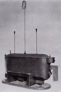
First, a little bit of history. The earliest radio control vehicle in history was designed by a man known well to Hackaday, Nikola Tesla. Tesla presented a radio controlled boat at an electrical exhibition in New York in 1898. Tesla called the system “Teleautomaton” and said the craft utilized a borrowed mind. In addition to cruising around a man made pond, the boat could solve equations by blinking lights atop two of its masts. Tesla would encourage viewers to call out math equations, then flash the lights from the boat’s control panel.

For many years R/C as well as its cousins Free Flight and control line were hobbies occupied solely by hackers. One needed to have metal machining skills to build engine parts, draftsman skills to read plans, and carpentry skills to build airframes. Radios were built from tubes. Control, if it may be called such, was all or nothing – so-called “bang-bang” systems. Much like their model railroad compatriots, R/C plane modelers built with the parts they had on hand. Several early DIY R/C planes were controlled by rotary telephone dials. Dial 1 to pull up, 2 to turn left, etc. Control surfaces were moved by rubber powered escapements rather than the servos we’ve come to know and love. Aerodynamics also came into play. With such rudimentary control systems, planes were designed to be inherently stable. Thankfully there were numerous proven air frame designs available from the free flight arena. Slow flight, high dihedral, and docile stall behavior were the rule of the day. Early R/C planes could be thought of as free flight vehicles with occasional suggestions via radio control. Click past the break to find out more about drone history, and to read about the recent FAA judgement.

Continue reading “Welcome To Droning On” →

The Tannin DIY MIDI Controller

tannin-ctlr

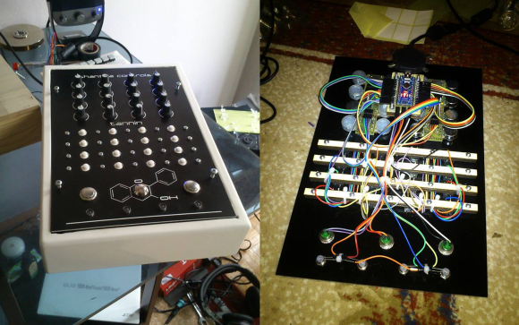
[Shantea] needed a DJ controller. While there are commercial controllers out there, none of them fit what he was looking for. He solved the problem by building the Tannin DIY MIDI controller. Tannin features 19 buttons, 16 potentiometers, and 4 LEDs. Buttons can send different MIDI messages for short presses and long presses. Pots can send 6 note on/off messages as well as MIDI control messages depending on their position. The LEDs blink in beat with the MIDI in clock. Everything is programmable and can be mapped thousands of different ways. The heart of the system is an Arduino Nano. [Shantea] used the hairless-midi library to convert MIDI to serial. The Arduino interfaces to a PC via serial over USB. On the host PC side, he ran loopbe30 to create a virtual MIDI cable to Traktor, his DJ software.

We love a build that looks just as good on the inside as on the outside, and Tannin doesn’t fail to impress in this respect. The frame is MDF, and the control panel is laser etched plastic on 3mm of Plexiglass. We really like Tannin’s flavone flair. Inside the case, wiring is kept organized and neat by zip ties and strips of wood below the button grid. [Shantea] had some noise issues connecting pots to flying wires, so he used a custom printed circuit board with a ground plane to gang the pots into 2 banks of 8. The results are something any controllerist would be proud of. Click past the break to see Tannin in action.

Continue reading “The Tannin DIY MIDI Controller” →