We’ve seen a lot of PCIe hacks on Hackaday, and a fair few of them boil down to hackers pulling PCIe somewhere it wasn’t meant to be. Today, we routinely can find PCIe x1, x2 and x4 links sitting around in our tech, thanks to the proliferation of things like NVMe SSDs, and powerful cheap SoCs that make PCIe appear at your fingertips.
In the PCIe For Hackers series, we’ve talked about PCIe and how cool it is, all the benefits it has for hackers, gave you layout and interconnection rules, and even went into things like PCIe switches and bifurcation. However, there’s one topic we didn’t touch much upon, and that’s external PCIe links.
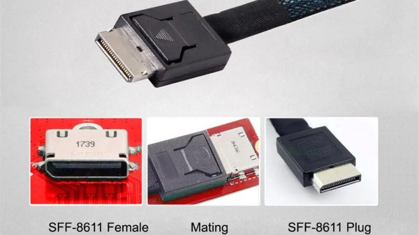
Today, I’d like to tell you about OCuLink – a standard that hackers might not yet know as an option whenever we need to pull PCIe outside of your project box, currently becoming all that more popular in eGPU space. Essentially, OCuLink is to PCIe is what eSATA is to SATA, and if you want to do an eGPU or an external “PCIe socket”, OCuLink could work wonders for you.
Respectable Capabilities
Just like any high-speed standard, PCIe has some tight requirements when things get fast. Even though PCIe is known to be not as sensitive to lower-quality links due to its link training and generation downgrade abilities, at higher link speeds, even through-hole vs SMD sockets can make a difference. So, if you want to go high-throughput, you want proper cabling and connectors, intended for out-of-chassis use – and OCuLink gives you all of this, at a low price.
Continue reading “PCIe For Hackers: External PCIe And OCuLink”