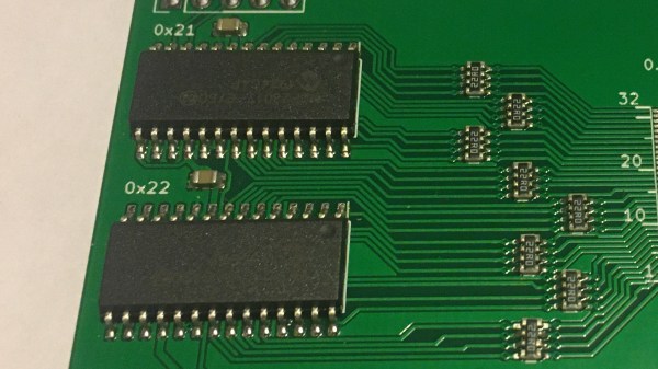
The MCP23017, a 16-bit I2C GPIO expander, has always been a tasty chip. With 16 GPIOs addressable over I2C, proper push/pull outputs, software-enabled pull-ups, eight addresses, maskable interrupts for all pins, and reasonably low price, there’s a reason it’s so popular. No doubt due in part to that popularity, it’s been consistently out of stock during the past year and a half, as those of us unlucky enough to rely on it in our projects will testify.
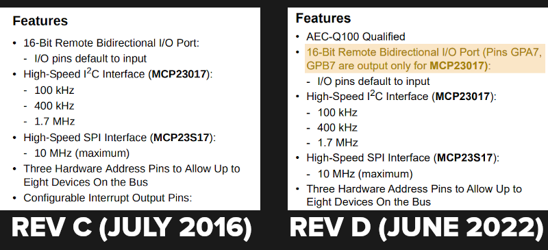
Now, the chip is back in stock, with 23,000 of them to go around on Mouser alone, but there’s a catch. Apparently, the lengthy out-of-stock period has taken a heavy toll on the IC. Whether it’s the recession or perhaps the gas shortages, the gist is — the MCP23017 now a 14/16-bit expander, with two of the pins (GPA7 and GPB7) losing their input capabilities. The chips look the same, are called the same, and act mostly the same — if you don’t download the latest version of the datasheet (Revision D), you’d never know that there’s been a change. This kind of update is bound to cause a special kind of a debugging evening for a hobbyist, and makes the chip way less suitable for quite a few applications.
It’s baffling to think about such a change happening nearly 20 years after the chip was initially released, and we wonder what could have caused it. This applies to the I2C version specifically — the SPI counterpart, MCP23S17, stays unaffected. Perhaps, using a microcontroller or shift registers for your GPIO expansion isn’t as unattractive of an option after all. Microcontroller GPIO errata are at least expected to happen, and shift registers seem to have stayed the same since the dawn of time.
The reasons for MCP23017 silicon getting cut in such a way, we might never know. At least now, hopefully, this change will be less of a bitter surprise to those of us happy to just see the chip back in stock — and for hackers who have already restocked their MCP23017 hoards, may your shelved boards magically turn out to have a compatible pinout.