Hoverboard Powered Sofa Is Fun And A Bit Dangerous

Discarded hoverboards are a great source of free high torque motors for hacking. This can include crazy but fun projects like this hoverboard-driven IKEA sofa, as demonstrated by [Bitluni] and his friends at xHain Hackerspace in Berlin.

With a couple of dead hoverboards in various conditions and a working e-bike battery, the group started exploring different options to put together a usable drivetrain. The first attempt involved commanding the motor drivers directly by intercepting communication from the gyro-based controller. The 9-bit communication protocol was a tough nut to crack, so they tried (and failed) to use the gyro-boards directly as the controllers. In the process of researching they discovered someone had created alternative firmware for the hoverboard controllers to allow control with a Wii Nunchuck. There is even a web-based config tool for compiling the firmware.

With some wood spacers screwed to the bottom of the sofa, the hoverboard motors could be attached by simply screwing their enclosure to the bottom of the couch and adding a section of PVC pipe between the halves for wiring. Caster wheels were added to the rear corners of the sofa to complete the chassis. The motors were very sensitive to control inputs on the Nunchuck, so riding the couch tended to rapidly turn into a rodeo event. The couch also wasn’t made to carry its load on the outer corners, so it had to be reinforced with plywood after it started cracking.

We’ve seen plenty of hacks that involve hoverboard motors, including an electric skateboard with mecanum wheels and a surprisingly practical e-bike conversion.

Continue reading “Hoverboard Powered Sofa Is Fun And A Bit Dangerous”

OpenDendrometer Can Measure How Your Tree Feels

There are various ways to measure plant health, and we’ve seen many projects creating open-source solutions. One we haven’t seen is a dendrometer, which involves measuring various physical dimensions of trees to track their health and growth. [John Opsahl] is changing this with the OpenDendrometer, a tool for tracking the diameter of tree limbs and fruit.

Tiny changes in diameter take place throughout the day, and tracking these changes allows deviations to be detected, which can be a sign of water stress. Over weeks and months, these measurements can be used to measure growth and fruits’ progress to harvest. [John] found that a digital tire tread depth gauge can work well for this application. Many of these gauges use the same electronics as the cheap digital calipers, for which the serial protocol was reverse engineered more than a decade ago. The OpenDendrometer connects the tire depth gauge to a microcontroller via a 1.5V level shifter, which logs measurements to an SD card while using a DS3231 RTC for accurate timestamps. The RTC can also be used to wake up the circuit at the required intervals to save battery power. For the initial proof of concept [John] is using an Arduino Pro Mini, but plans to move to an ESP32 at a later stage to allow wireless data transmission.

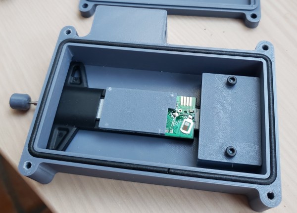
Everything will be housed in a 3D printed enclosure with a foam cord gasket to make the device weather resistant. A mounting rod on the outside of the enclosure with adjustable thumbscrews allows the OpenDendrometer to be attached to any part of the tree. We plan to keep an eye on this project and look forward to seeing the data it produces.

For the other ways of measuring plant health, we’ve covered everything from soil moisture to Normalized Difference Vegetation Index and even plant weight and even pot plant weight.

Simple Propulsion For The Lazy Paddle Boarder

One of the downsides to healthy outdoor activities is all the exercise. Who would want to do that if you can build something to do the hard work for you? That seems to be the theme of [Bitluni]’s latest build, a simple (and hacky) propulsion system for a stand-up paddleboard.

After acquiring an inflatable stand-up paddleboard and trying it out a few times, [Bitluni] decided to skip the “stand up” and “paddle” parts. He designed and printed a very simple propeller, which he intended to power with a brushless motor and speed controller. In the process of drilling out the prop to fit the shaft, he realized he was overcomplicating things. So he decided to just use his battery-powered drill instead. For the shaft tube, he modified an old crutch by drilling a hole in the handle for the shaft and adding a duct with a bearing on the other end. He also attached a carabiner to the handle to fix it to the paddleboard.

A test at a lake showed that the propulsion system performed relatively well for a proof of concept but had some flaws. To submerge it properly, [Bitluni] had to sit on the rear of the paddleboard facing backward. If it was too close to the surface, it would suck air and lose thrust, or spray him and his drill with water. Of course, there is also the real risk of drowning his drill in the process.

Projects don’t need to be complex to be enjoyable, and you can often learn more by quickly creating a proof of concept instead of taking forever to come up with the “perfect” design.

If you want to see some more advanced water-borne projects, check out the waterjet-powered electric surfboards built by [RCLifeOn] and [Andrew W].

Continue reading “Simple Propulsion For The Lazy Paddle Boarder”

R2Home Is Ready To Bring Back Your High Altitude Payload

With high-altitude ballooning, you are at the mercy of the winds, which can move your payload hundreds of kilometers and deposit it in some inaccessible spot. To solve this [Yohan Hadji] created R2Home, an autonomous parachute-based recovery system that can fly a payload to any specified landing site within its gliding range.

We first covered R2Home at the start of 2021, when he was still in the early experimental phases, but the project has matured massively since then. It just completed its longest and highest test flight. Descending autonomously from a release altitude of 3500 m, with an additional radiosonde payload, it landed within 5 m of the launch point.

R2Home electronics with it's insulated enclosure
R2Home electronics with its insulated enclosure

R2Home can fly using a variety of steerable canopies, even a DIY ram-air parachute, as demonstrated in an earlier version. [Yohan] is currently using a high-performance wing for RC paragliders.

A lot of effort went into developing a reliable parachute deployment system. The main canopy is packed carefully in a custom “Dbag”, which is attached to a drogue chute to stabilize the system during free-fall and deploy the main canopy at a preset altitude. This is done with a servo operated release mechanism, while steering is handled by a pair of modified winch servos intended for RC sailboats.

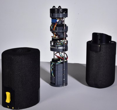
All the electronics are mounted on a stack of circular 3D printed brackets which fit in a tubular housing, bolted together with threaded rods. With the help of a design student [Yohan] also upgraded the simple tube housing to a lockable, foam-insulated design to help it handle temperatures at high altitudes.

The flight main flight computer is a Teensy 4.1  plugged into a custom PCB to connect all the navigation, communication, and flight systems. The custom Arduino-based autopilot takes inputs from a GPS receiver, and pilots the system to the desired drop zone, which it circles until touchdown.

The entire project is extremely well documented, and all the design files and code are open source and available on Github. Continue reading “R2Home Is Ready To Bring Back Your High Altitude Payload”

Trippy Bicycle Uses Multiple Partial Wheels

Bicycles need at least two wheels to be rideable, but [The Q] realized you don’t necessarily need the wheels to be in one piece. As long as you have at least two points of rolling contact with the ground, you can spread the load across multiple partial wheels. He demonstrated this by splitting the rear wheel of his bike first in half and then thirds to create an absolute head turner.

Since a conventional bicycle wheel with tensioned spokes would collapse if cut apart, [The Q] used single-piece aluminum wheels instead. The tires were cut into pieces, and the inner tubes were replaced with sections of thick-walled HDPE pipe that won’t collapse under the weight of a human. The tires and the HDPE “inner tubes” were riveted to the wheels.

To mount the additional wheels on the frame, [The Q] welded a set of extensions to the back with mounting points for the partial wheels. To keep them synced, timing is done with chains running on sprockets welded to the disc brakes. In the second video, he tries to also split the front wheels, but found the front forks can’t handle the torque and would flex dangerously when the contact point is too far forward. Instead, he settled for three wheels on the back.

Much like his hubless bicycle, it’s not designed to be better than a standard bicycle, but is excellent for attracting attention. Though at least in some situations, the all-wheel drive bike he built last year might come in handy.

Continue reading “Trippy Bicycle Uses Multiple Partial Wheels”

Turning A Pair Of Syringes Into A Tiny Water Pump

There is something inherently fascinating about tiny mechanical devices, especially when you’re used to seeing much larger versions. This is the case with [Penguin DIY]’s tiny centrifugal water pump built from 5 ml syringes.

The pump is powered by a small 8 mm diameter brushed DC motor, likely the same type that is used for small toy-grade quadcopters. The tiny impeller is a section of the syringe’s original plunger, with its cross-shaped body acting as the impeller blades. [Penguin DIY] first experimented with the original plunger seal to protect the motor from water, but it quickly melted from friction with the spinning shaft. Silicone sealant was used instead, and the motor shaft was covered with a layer of oil to prevent the sealant from sticking to it. Then the blob of sealant was flattened with a translucent plastic disc to allow clearance for the impeller.

A hole was drilled in the side of the syringe where the impeller sits, and a nozzle cut from the tip of another syringe was glued in place as the outlet. It’s notoriously difficult to get anything to stick to polypropylene syringes, but [Penguin DIY] says in the comments he was able to find an “organic superglue” that worked. With the motor and impeller inserted, the remaining space was also sealed with silicone.

This tiny pump packs a surprising amount of power, and was able to empty a 1.5 l bottle in about one minute with enough pressure to send the jet of water flying. There are still some issues that need to be addressed, though. With the motor completely sealed, it could burn itself quite quickly. A commenter also mentioned that it might suck water into the motor past the shaft after a hot run, as the air inside the motor cools and contracts. Even so, this little pump might be practical for applications that only require short runs, like watering potted plants. If you need more power you could always 3D print a larger pump.

Continue reading “Turning A Pair Of Syringes Into A Tiny Water Pump”

Large Format 3D Printer Is A Serious Engineering Challenge

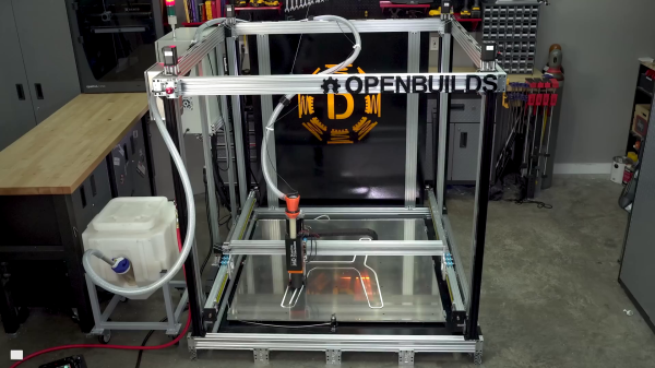
When you want to build a large format 3D printer, you can’t just scale up the design of a desktop machine. In an excellent four-part build series (videos after the break), [Dr. D-Flo] takes us through all the engineering challenges he had to contend with when building a 3D printer with a 4x4x4 ft (1.2 m cube) print volume.

For such a large print volume you won’t be printing with a 0.4 mm nozzle. The heart of the printer is a commercial Massive Dimension MDPH2 pellet extruder, capable of extruding ~1 kg of plastic per hour through 1.5 mm to 5 mm nozzles. To feed the extruder, [Dr. D-Flo] used a Venturi vacuum system to periodically suck pellets from a large hopper. The system is driven by compressed air, which can introduce moisture back into the carefully dried pellets. To reduce the humidity levels, the compressed air passes through a series of vertical aluminum tubes to allow moisture to condense and drain out the bottom.

At 8.4 kg, it needs a powerful motion platform to move it. [Dr. D-Flo] went with a stationary bed design, with the extruder pushed around by seven high torque NEMA23 motors on a large gantry built from C-beam aluminum extrusions. A machine this size needs to be very rigid with well-fitting parts, so [Dr. D-Flo] made heavy use of CNC machined aluminum parts.

To allow dynamic bed leveling, [Dr. D-Flow] made use of a Quad Gantry Leveling (GQL) scheme. This means that each of the four Z-actuators will dynamically adjust its position based on inputs from the leveling probe. The avoid stressing the corner mountings that hold the X-Y gantry to the Z carriage plates, he used radial spherical bearings at the mounting points to allow a few degrees of play.

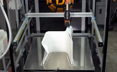
The build plate consists of an aluminum plate bolted onto the base in 25 positions with springs for adjustability. A massive 6000 watt 220 V heating pad sticks to the bottom, while the actual printing surface is a large sheet of borosilicate glass. One major concern was the deflection of the build plate when heated to working temperature, but with all the adjustment options [Dr. D-Flo] was able to get height variation down to about 0.25 mm. This is within the acceptable range when printing with layer heights of 1 mm or more.

We’ve featured large scale 3D printers in the past, but none are quite as big the University of Maine’s building-sized 3D printer that can print a motorboat in one piece.

Continue reading “Large Format 3D Printer Is A Serious Engineering Challenge”