A CO2 Traffic Light On An SAO

[David Bryant] clearly has an awareness of the impact of an excess concentration of CO2 in the local environment and has designed an SAO board to add a CO2 traffic light indicator to one of the spare slots on the official Hackaday Supercon 2024 badge.

The part used is the Sensirion SCD40 ‘true’ CO2 sensor, sitting atop an Adafruit rider board. [David] got a leg up on development by creating a simple SAO breakout board, which could have either the male and female connectors fitted, as required. Next, he successfully guessed that the badge would be based around the RP2040 running MicroPython and hooked up an Adafruit Feather RP2040 board to get started on some software to drive the thing. This made hooking up to the official badge an easy job. Since the SAO has only two GPIOs, [David] needed to decode these to drive the three LEDs. There are a few ways to avoid this, but he wanted to relive his earlier EE college years and do it the direct way using a pair of 74HC00 quad NAND gate chips.

We’ve seen a few CO2 monitors over the years. This sleek little unit is based around the Seeeduino XIAO module and uses an LED ring as an indicator. Proper CO2 monitors can be a little pricey, and there are fakes out there. Finally, CO2 is not the only household pollutant; check out this project.

PicoROM, A DIP-32 8-Bit ROM Emulator

As we all know, when developing software for any platform or simply hacking a bit of code to probe how something works, the ability to deploy code rapidly is a huge help. [Martin Donlon], aka [wickerwaka], is well known in retro gaming and arcade hardware reverse engineering circles and had the usual issues figuring out how an arcade CPU board worked while developing a MiSTer core. Some interesting ASICs needed quite a bit of poking, and changing the contents of socketed ERPOMs is a labour-intensive process. The solution was PicoROM, a nicely designed ROM emulator in a handy DIP-32 form factor.

As the title suggests, PicoROM is based on the Raspberry Pi RP2040. It emulates an 8-bit ROM up to 2MBits in size with speeds up to 100ns. Since it uses the RP2040, USB connectivity is simple, enabling rapid uploading of new images to one (or more) PicoROMs in mere seconds. A vertically orientated USB-C connector allows multiple PicoROMs to be cabled to the host without interfering with neighbouring hardware. The firmware running on core 1 passes data from the internal 264K SRAM, using the PIO block as a bus interface to the target. A neat firmware feature is the addition of a mechanism to use a ROM region as a bidirectional control channel, which the software running on the target can use to communicate back to the host computer. This allows remote triggering of actions and the reporting of responses. Responses which may not be physically observable externally. [Martin] is using this feature extensively to help probe the functionality of some special function chips on the target boards, which is still a slow process but helped massively by reducing that critical software iteration time. The PCB was designed with KiCAD. The project files for which can be found here.

This isn’t the first time we’ve seen the RP2040 used for ROM emulation; here’s a pile of wires that does the same job. It just isn’t as pretty. Of course, if you really must use EPROMs, then you could give this sweet programmer a look over.

Continue reading “PicoROM, A DIP-32 8-Bit ROM Emulator”

The Tsushin Booster – A PC Engine Modem Add-on With A Twist

Sometimes, hardware projects get cancelled before they have a chance to make an impact, often due to politics or poor economic judgment. The Tsushin Booster for the PC Engine is one such project, possibly the victim of vicious commercial games between the leading Japanese console manufacturers at the tail end of the 1980s. It seems like a rather unlikely product: a modem attachment for a games console with an added 32 KB of battery-backed SRAM. In addition to the bolt-on unit, a dedicated software suite was provided on an EPROM-based removable cartridge, complete with a BASIC interpreter and a collection of graphical editor tools for game creation.

Internally, the Tsushin booster holds no surprises, with the expected POTS interfacing components tied to an OKI M6826L modem chip, the SRAM device, and what looks like a custom ASIC for the bus interfacing.

It was, however, very slow, topping out at only 1200 Baud, which, even for the period, coupled with pay-by-minute telephone charges, would be a hard sell. The provided software was clearly intended to inspire would-be games programmers, with a complete-looking BASIC dialect, a comms program, a basic sprite editor with support for animation and 
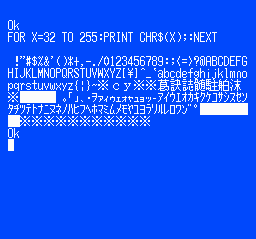
even a map editor. We think inputting BASIC code via a gamepad would get old fast, but it would work a little better for graphical editing.

PC Engine hacks are thin pickings around these parts, but to understand a little more about the ‘console wars’ of the early 1990s, look no further than this in-depth architectural study. If you’d like to get into the modem scene but lack original hardware, your needs could be satisfied with openmodem. Of course, once you’ve got the hardware sorted, you need some to connect to. How about creating your very own dial-up ISP?

An RP2040-based PC-FX Development Cartridge

[David Shadoff] has a clear soft spot for the NEC console systems and has been collecting many tools and data about them. When developing with these old systems, having a way to upload code quickly is a real bonus, hence the creation of the PC-FX Dev Cart. Based on the Raspberry Pi RP2040, the custom cartridge PCB has everything needed to run software uploadable via a USB-C connection.

While the PC-FX is a CDROM-based system, it does sport a so-called FX-BMP or backup memory port cartridge slot, which games can use to save state and perform other special functions. Under certain circumstances, the PC-FX can be instructed to boot from this memory space, and this cartridge project is intended to enable this. Having a quick way to upload and execute code is very useful when exploring how these old systems work, developing new applications, or improving the accuracy of system emulators. The original FX-BMP cartridge has little more inside than a supercapacitor-backed SRAM and a custom interfacing IC, and of course, it would be quite a hassle to use this to develop custom code.

Continue reading “An RP2040-based PC-FX Development Cartridge”

Bakelite To The Future – A 1950s Bluetooth Headset

A decade ago, [Jouke Waleson] bought a Dutch ‘model 1950’ PTT (The Dutch Postal Service) rotary-dial telephone of presumably 1950s vintage manufactured by a company called Standard Electric, and decided it would be neat to hack it to function as a Bluetooth hands-free device. Looking at the reverse, however, it is stamped “10.65” on the bottom, so maybe it was made as recently as 1965, but whatever, it’s still pretty old-tech now.

A well-specified transformer?

The plan was to utilise ESP32 hardware with the Espressif HFP stack to do all the Bluetooth heavy lifting. [Jouke] did find out the hard way that this is not a commonly-trodden path in hackerland, and working examples and documentation were sparse, but the fine folks from Espressif were on hand via GitHub to give him the help he needed. After ripping into the unit, it was surprisingly stuffed inside there. Obviously, all the switching, even the indication, was purely electromechanical, which should be no surprise. [Jouke] identified all the necessary major components, adding wires and interfacing components as required, but was a bit stumped at the function of one funky-looking component that we reckon must be a multi-tap audio transformer, oddly finished in baby pink! After renovating some interesting cross-shaped mechanical indicators and wiring up some driving transistors, it was time to get on to the audio interface. Continue reading “Bakelite To The Future – A 1950s Bluetooth Headset”

Use PicoGlitcher For Voltage Glitching Attacks

We see a fair few glitcher projects, especially the simpler voltage glitchers. Still, quite often due to their relative simplicity, they’re little more than a microcontroller board and a few components hanging off some wires. PicoGlitcher by Hackaday.IO user [Matthias Kesenheimer] is a simple voltage glitcher which aims to make the hardware setup a little more robust without getting caught up in the complexities of other techniques. Based on the Raspberry Pico (obviously!), the board has sufficient niceties to simplify glitching attacks in various situations, providing controllable host power if required.

A pair of 74LVC8T245 (according to the provided BoM) level shifters allow connecting to targets at voltages from 1.8 V to 5 V if powered by PicoGlitcher or anything in spec for the ‘245 if target power is being used. In addition to the expected RESET and TRIGGER signals, spare GPIOs are brought out to a header for whatever purpose is needed to control a 
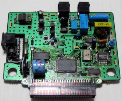
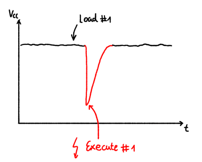
particular attack. If a programmed reset doesn’t get the job done, the target power is provided via a TPS2041 load switch to enable cold starts. The final part of the interface is an analog input provided by an SMA connector.

The glitching signal is also brought out to an SMA connector via a pair of transistors; an IRLML2502 NMOS performs ‘low power’ glitching by momentarily connecting the glitch output to ground. This ‘crowbarring’ causes a rapid dip in supply voltage and upsets the target, hopefully in a helpful way. An IRF7807 ‘NMOS device provides a higher power option, which can handle pulse loads of up to 66A. Which transistor you select in the Findus glitching toolchain depends on the type of load connected, particularly the amount of decoupling capacitance that needs to be discharged. For boards with heavier decoupling, use the beefy IRF7807 and accept the glitch won’t be as sharp as you’d like. For other hardware, the faster, smaller device is sufficient.

The software to drive PicoGlitcher and the hardware design files for KiCAD are provided on the project GitHub page. There also appears to be an Eagle project in there. You can’t have too much hardware documentation! For the software, check out the documentation for a quick overview of how it all works and some nice examples against some targets known to be susceptible to this type of attack.

For a cheap way to glitch an STM8, you can just use a pile of wires. But for something a bit more complicated, such as a Starlink user terminal, you need something a bit more robust. Finally, voltage glitching doesn’t always work, so the next tool you can reach for is a picoEMP.

Continue reading “Use PicoGlitcher For Voltage Glitching Attacks”

Can You Homebrew A Running Shoe?

Unless you spend all your time lounging on the sofa, you probably own at least one pair of shoes. But have you ever thought to make your own to improve some aspect of your life? YouTube channel Answer in Progress set out to do precisely that, but it didn’t quite work out.

When you (well, other people) get into running, it’s tempting to believe a lot of the shoe company hype and just drop hundreds of dollars on the latest ‘super shoe’ and hope that will help you break your target time. But do you actually need to buy into all this, or can you make something yourself? The project aimed to get the 5k time down significantly, at any cost, but primarily by cheating with technology. The team set out to look at the design 
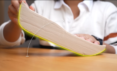
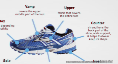
process, given that there is indeed a fair amount of science to shoe design. Firstly, after a quick run, the main issues with some existing shoes were identified, specifically that there are a lot of pain points; feet hurt from all the impacts, and knees take a real pounding, too. That meant they needed to increase the sole cushioning. They felt that too much energy was wasted with the shoes not promoting forward motion as much as possible; feet tended to bounce upwards so that a rocker sole shape would help. Finally, laces and other upper sole features cause distraction and some comfort issues, so those can be deleted.

A thicker mid-sole allows for a rolled shape

The plan was to make a ‘sock’ shoe style, with an upper in one piece and stretchy enough to slip on without laces. The process started by wrapping the foot in cling film and then a few layers of duct tape to fix the shape. This was split down the top to extract the foot, open out the pattern, and transfer it to some nylon fabric. The outer profile was transferred and cut out with simple hand tools in a fashion that would allow the shape to be reconstructed as it was glued to a sole. It sounds simple, but it’s pretty fiddly work.
Continue reading “Can You Homebrew A Running Shoe?”