Calculators are so ubiquitous and so familiar that they are easy to take for granted in many different ways. [lcamtuf] points out one that has probably never occurred to many of us: the user interface for a calculator is an unexpectedly complex thing.
Resolving something like 1 + 2 = is pretty straightforward but complexity compounds rapidly after that, with numerous special cases. Let’s imagine one decides to program a simple calculator UI as a weekend project. The development process might look a little like this:
- User types in
1 + 2 =and the calculator displays3. What happens if the user immediately presses-? - No problem, just consider the result of the previous operation as an already-there input. So we’ll have
3 -for this next operation, and wait for more. - Unless we should have treated that
-as a negative sign for whatever number is coming next, making it a negative number? No, ignore that. Just treat whatever results from pressing equals as a pre-typed input. - Unless the user hits a number. Because if they hit
2(for example) then we’ll have a32and not a2which they probably, definitely don’t expect. So that’s a special case and we should insert a clear if that happens. - Oh, better clear if the user enters a decimal, too.
- I’m going to need a coffee…
And that’s just the tip of the iceberg. Imagine trying to figure all this out for the very first time, without the benefits of habit and history to fall back on.
The fact is that supporting the apparently trivial behavior of a simple calculator requires an underlying complex state machine that deals with all kinds of special cases in order to make the UI feel intuitive. And that’s just for a basic four-function calculator; we haven’t even touched on how special keys like % should behave.
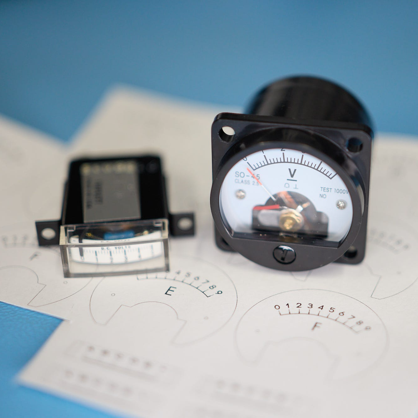
We know [lcamtuf] speaks from experience, not just because of their deep knowledge of calculator history but because they rolled their own calculator that uses voltmeters as digit displays and there’s nothing like actually implementing something to make one appreciate it.