Review: JYE Tech DSO150 Oscilloscope Kit

When men were men, and oscilloscopes were oscillographs.

Do you remember your first oscilloscope? Maybe we have entered the era in which younger readers think of a sleek model with an LCD screen, but for the slightly older among us the image that will come to mind is likely to be a CRT-based behemoth. Mine was a 2MHz bandwidth Cossor from the 1950s, wildly outdated by the 1980s, but it came to me at no cost. It proudly proclaims itself as a “Portable Oscillograph”, but requires its owner to be a weightlifter to move it. I still have it, as a relic and curio.

For most of us a new ‘scope is still a significant investment. Even affordable current models such as the extremely popular Rigol instruments are likely to cost several hundred dollars, but offer measurement functions undreamed of by those 1950s engineers who would have looked on the Cossor as an object of desire.

Oscilloscope buyers on a budget may not have the cash for a Rigol, a Hantek, or any of the other affordable ‘scopes. Someone starting on the road of electronic engineering can scout around for a cheap or free second-hand CRT model, but thanks to the ever advancing march of technology they also have another option. Modern microprocessors and microcontrollers have analogue-to-digital converters and processor cores that are fast enough to provide the functions of a simple oscilloscope, and to that end a variety of very cheap ‘scopes and ‘scope kits have come on the market. These invariably have a rather small LCD screen and a relatively low bandwidth, but since they can be had for almost pocket-money prices their shortcomings can be overlooked in the name of value. It’s been a matter of curiosity for some time then: are these instruments any good? For around £16 ($21) and the minor effort of an online order from China, we decided to find out.

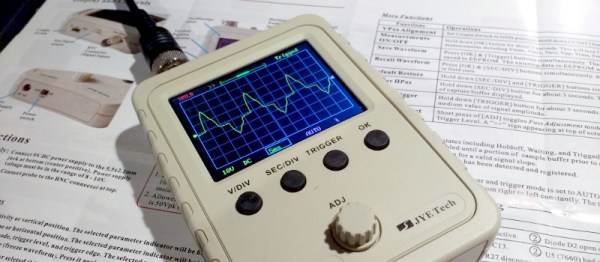
If you look at most stockists of electronic kits these days, you are likely to find an oscilloscope kit in their range. These are volume produced in China, and the same design trends appear across different models. You can buy surface mount or through-hole, and most of them feature a bare board with maybe a piece of laser-cut Perspex standing in for a case. There are one or two models appearing that come with a case though, and it was one of these that we ordered. The JYE Tech DSO150 is a single-channel ‘scope with a 2.4″ 320×240 pixel colour LCD screen and a 200kHz bandwidth. Its specification is typical of the crop of similar kits, though its smart case sets it apart and made it an easy choice.

In the Box

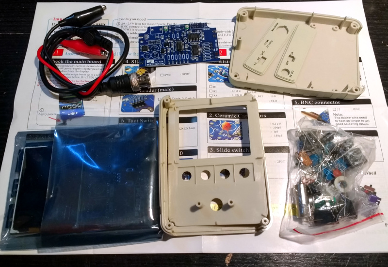
We ordered one, and when it arrived, it was packed in a small cardboard carton that had suffered some crushing in transit, but had protected the internal contents well enough that no harm had been done. A layer of foam protected the LCD, and the case parts appeared rigid enough to protect the rest of the components. There was a bag of discretes, the case parts, two PCBs, a test lead with crocodile clips, and two pages of instructions.

When looking at a kit, it’s best to start with the instructions, because no matter the quality of the kit itself it is the quality of the instructions that make or break a kit. If you can’t build it then it doesn’t matter how good it might be, it’s effectively junk.

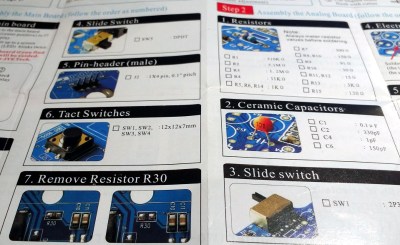
The DSO150 instructions are two sheets of high quality double-sided colour print, with the emphasis on pictures rather than words, The front page introduces the kit and gives a quick soldering guide, then the next two pages step through each stage of construction. The final page has basic instructions for use, specification, and a troubleshooting guide. Our kit had all surface-mount parts already fitted, if we’d known the kit could also be had with SMD parts to fit we’d have bought that version instead.

Inside the DSO100.
Inside the DSO100.

The instruction steps are long on images and short on text, but there are sometimes few cues as to where the component in question lies on the board. Sometimes some careful examination of board and picture is necessary to ensure correct placement. The first step though doesn’t involve any soldering, wire the main board up to a 9V supply, and watch the LCD boot into the oscilloscope software. There is support via a forum on the JYE Tech website, we presume you’d go there if it failed to boot out of the box. A 9V PSU isn’t included, you’ll need to find one with a 2.1mm centre positive plug. Fortunately a suitable candidate was in the box of wall warts here, formerly being used by a router.

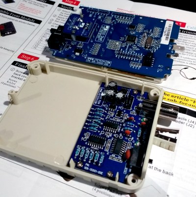
The main board assembly is straightforward enough, being the assembly of larger through-hole parts such as switches and connectors. The analogue board has a brace of small through-hole resistors and ceramic capacitors to fit, of these the resistors were of the tiny variety which made distinguishing between some of their colour stripes a little difficult. Bring your multimeter to check. There is a BNC connector that requires significant heat on there too, so make sure you have a suitably beefy iron to hand. Finally there is a small board for the rotary encoder, then the front of the case can be assembled to the main board, the analogue board attached, and the ‘scope set up. Verify on-board voltages, attach the test clip to the calibration output and adjust the compensation capacitors for a square wave, and the rest of the case can be added to complete the unit.

Functionality

The DSO150 showing the upper end of its bandwidth.

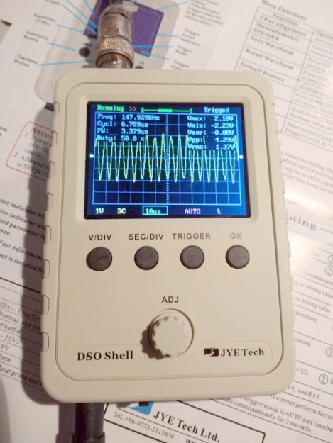
In use, the DSO150 makes a simple and straightforward enough oscilloscope. The usual volts/division and timebase selection is easy enough, and the various trigger modes can quickly be selected. If you’ve used an oscilloscope before then you will have no problems getting started with it. But of course, the DSO150 isn’t just a simple oscilloscope, it’s a digital storage ‘scope. And with 1024 sampling points it can do the usual storage ‘scope thing of allowing the user to examine a stored waveform in great detail, scrolling back and forth through the stored points. Here the instruction sheet falls short, not mentioning that a double tap on the V/div or Sec/div buttons allows you to scroll.

Connecting the signal generator to our DSO150 allowed the exploration of its bandwidth. The claimed 200kHz is pretty spot-on, winding the signal generator far beyond that point showed a tail-off in displayed amplitude. Also the minimum 10µS per division limits the usefulness of a waveform display at these frequencies.

The DSO150 is supplied with a short test lead terminated in a pair of crocodile clips. This is somewhat less useful than the oscilloscope probes we’re used to, though happily it can also be used with a standard 1x/10x probe. Looking at the square wave on the test terminal through a standard probe reveals a sharp corner on the waveform, so there seems not to be any problems between the compensation on-board and that in the probe. It’s likely that either the DSO150 here will be used with a standard probe, or that the crocodile clip will swiftly be replaced with a probe of some kind.

Closing Thoughts

So then, the JYE Tech DSO150 oscilloscope kit. A nice little ‘scope within the limitations of the STM32F103C8 microcontroller that drives it. If you can put up with a 200kHz bandwidth and a 50V peak input voltage then it’s a useful pocket instrument. Its calibration will depend on the STM’s crystal and voltage reference, but as with the rest of its specification, when you consider its pocket-money price those become minor considerations. Add in that its software is open-source, and you have a very nice platform indeed. If we wanted to nitpick we’d ask for a battery compartment and a proper probe, but since both of those would put up the price we wouldn’t make too much noise about it. If you need a pocket ‘scope to supplement your bench scope when working on lower frequencies, or if you have a youngster in the family looking for their first ‘scope, buy one! Our review unit will definitely see some use rather than gathering dust.

Why You Shouldn’t Quite Forget The Moving Coil Multimeter

Did any of you have an AWS multimeter? Was it the best? Radio-electronics magazine, August 1981.
Did any of you have an AWS multimeter? Was it the best? Radio-Electronics magazine, August 1981.

If you were to ask a random Hackaday reader what their most fundamental piece of electronic test equipment was, it’s likely that they would respond with “multimeter”. If you asked them to produce it, out would come a familiar item, a handheld brick with a 7-segment LCD at the top, a chunky rotary selector switch, and a pair of test probes. They can be had with varying quality and features for anything from a few dollars to a few hundred dollars, though they will nearly all share the same basic set of capabilities. Voltage in both AC and DC, DC current, resistance from ohms to mega ohms, and maybe a continuity tester. More expensive models have more features, may be autoranging, and will certainly have better electrical safety than the cheaper ones, but by and large they are a pretty standard item.

If Hackaday had been around forty years ago and you’d asked the same question, you’d have had a completely different set of multimeters pulled out for your inspection. Probably still a handheld brick with the big selector switch, but instead of that LCD you’d have seen a large moving-coil meter with a selection of scales for the different ranges. It would have done substantially the same job as the digital equivalent from today, but in those intervening decades it’s a piece of equipment that’s largely gone. So today I’m going to investigate moving coil multimeters, why you see them a lot less these days than you used to, and why you should still consider having one in your armoury. Continue reading “Why You Shouldn’t Quite Forget The Moving Coil Multimeter”

Build A Calculator, 1974 Style

Last month we touched upon the world of 1970s calculators with a teardown of a vintage Sinclair, and in the follow-up were sent an interesting link: a review of a classic Sinclair calculator kit from [John Boxall]. It’s a few years old now, from 2013, but since it passed us by at the time and there was clearly some interest in our recent teardown, it’s presented here for your interest.

It seems odd in 2017 that a calculator might be sold as a kit, but when you consider that in the early 1970s it would have represented an extremely expensive luxury purchase it makes some sense that electronics enthusiasts who were handy with a soldering iron might consider the cost saving of self-assembly to be worthwhile. The £24.95 price tag sounds pretty reasonable but translates to nearly £245 ($320) in today’s terms so was hardly cheap. The calculator in question is a Sinclair Cambridge, the arithmetic-only predecessor to the Sinclair Scientific we tore down, and judging by the date code on its display driver chip it dates from September 1974.

As a rare eBay find that had sat in storage for so long it was clear that some of the parts had suffered a little during the intervening years. The discrete components were replaced with modern equivalents, including a missing 1N914 diode, and the display was secured in its flush-fitting well in the board with wire links. The General Instrument calculator chip differs from the Texas Instruments part used in the Scientific, but otherwise the two calculators share many similarities. A full set of the notoriously fragile Sinclair battery clips are in place, with luck they’ll resist the urge to snap. A particularly neat touch is the inclusion of a length of solder and some solder wick, what seems straightforward to eyes used to surface-mount must have been impossibly fiddly to those brought up soldering tube bases.

The build raises an interesting question: is it sacrilege to take a rare survivor like this kit, and assemble it? Would you do it? We’d hesitate, maybe. But having done so it makes for a fascinating extra look at a Sinclair Cambridge, so is definitely worth a read. If you want to see the calculator in action he’s posted a video which we’ve put below the break, and if you need more detail including full-resolution pictures of the kit manual, he’s put up a Flickr gallery.

Continue reading “Build A Calculator, 1974 Style”

Teardown With A Twist: 1975 Sinclair Scientific Calculator

When writing a recent piece about Reverse Polish Notation, or RPN, as a hook for my writing I retrieved my Sinclair Scientific calculator from storage. This was an important model in the genesis of the scientific calculator, not for being either a trailblazer or even for being especially good, but for the interesting manner of its operation and that it was one of the first scientific calculators at an affordable price.

I bought the calculator in a 1980s rummage sale, bodged its broken battery clip to bring it to life, and had it on my bench for a few years. Even in the early 1990s (and even if you didn’t use it), having a retro calculator on your bench gave you a bit of street cred. But then as life moved around me it went into that storage box, and until the RPN article that’s where it stayed. Finding it was a significant task, to locate something about the size of a candy bar in the storage box it had inhabited for two decades, among a slightly chaotic brace of shelves full of similar boxes.

The Sinclair's clean design still looks good four decades later.
The Sinclair’s clean design still looks good four decades later.

Looking at it though as an adult, it becomes obvious that this is an interesting machine in its own right, and one that deserves a closer examination. What follows will not be the only teardown of a Sinclair Scientific on the web, after all nobody could match [Ken Shirriff]’s examination of the internals of its chip, but it should provide an insight into the calculator’s construction, and plenty of satisfying pictures for lovers of 1970s consumer electronics.

The Sinclair is protected by a rigid black plastic case, meaning that it has survived the decades well. On the inside of the case is a crib sheet for its RPN syntax and scientific functions, an invaluable aid when it comes to performing any calculations.

It shares the same external design as the earlier Sinclair Cambridge, a more humble arithmetic calculator, but where the Cambridge’s plastic is black, on the Scientific it is white. The LED display sits behind a purple-tinted window, and the blue-and-black keyboard occupies the lower two-thirds of the front panel. At 50 x 111 x 16 mm it is a true pocket calculator, with an elegance many of its contemporaries failed to achieve and which is certainly not matched by most recent calculators. Good industrial design does not age, and while the Sinclair’s design makes it visibly a product of the early 1970s space-age aesthetic it is nevertheless an attractive item in its own right.

Continue reading “Teardown With A Twist: 1975 Sinclair Scientific Calculator”

An Amstrad PCW For The 21st Century

If you were a computer-mad teen in the late 1980s, you were probably in the process of graduating from an 8-bit machine to a 16-bit one, maybe an Amiga, or an Atari ST. For the first time though you might not have been the only computer owner in your house, because there was every chance your parents might have joined the fun with a word processor. Maybe American home offices during this period might have had PC clones, but for Brits there was every chance that the parental powerhouse would have been an Amstrad PCW.

Amstrad were the masters of packaging up slightly outdated technology for electronic consumers on a budget, and the PCW was thus a 1970s CP/M machine for the 1980s whose main attraction was that it came with monitor and printer included in the price. [James Ots]’ parents had one that interested him enough that  he has returned to the platform and is documenting his work bringing it up to date.

It was the most recent progress in booting into CP/M from an SD card by hijacking the printer ROM that caught our eye, but reading all the build logs that is only the tip of the iceberg. He’s connected another monitor, made a joystick port and a soundcard, and added a memory upgrade to his PCW. Most of these machines would have only been used with the bundled word processor, so those are real enhancements.

We’ve featured quite a few projects involving Amstrad’s CPC home computers, such as this one with a floppy emulator. Amstrad are an interesting company for followers of consumer electronics of the ’70s and ’80s, they never had the out-there tech wackiness of their great rival Sinclair but their logo could be found on an astonishing variety of appliances. The “AMS” in Amstrad are the initials of the company founder [Alan Sugar], who is rather better known in 2017 as the British host of The Apprentice. It is not known whether he intends to lead the country.

Scratch That SDR!

When you think of a software defined radio, what language might you consider reaching for to create the software part of the equation? C? C++, maybe?

How about Scratch?

“What, Scratch as in the visual programming language aimed at young people?”, we hear you cry incredulously. It’s not exactly the answer you’d expect for an SDR, but thanks to [Andrew Back]’s work there is now ScratchRadio, a set of Scratch extensions for software defined radio. Why on earth do this? The aim is to lower the barrier to entry for software defined radio as far as possible, and to place it in a learning environment such as Scratch seems an ideal way to achieve that.

Of course, Scratch itself isn’t powerful enough for the heaviest of heavy lifting, so in reality this is a Scratch wrapper for a LuaRadio backend. It was created with the LimeSDR Mini in mind, but given that LuaRadio is not specific to that hardware we’d expect it to work with other SDRs such as the ever-popular RTL chipset TV sticks. It gives an owner of a Raspberry Pi 3 the ability to experiment with SDR coding without the need for a huge level of experience, and that to our mind can only be a good thing.

If you fancy trying ScratchRadio, you can find the code in its GitHub repository, and take it from there. Meanwhile we covered LuaRadio last year, so if Scratch is a little basic for you and GNU Radio too advanced, give it a try.

Radio icon: [Sakurambo], (CC BY-SA 3.0).

Scratch cat logo: MIT Media Lab.

Is It A MagLite Or A MagnaStat?

[David Schneider]’s love affair with Weller temperature controlled soldering irons began many years ago, but when he came to the point of needing a cordless iron he had problems finding one that replicated his trusty mains-powered soldering station. His solution was simple, to build his own, and in a stroke of genius he did so with an odd combination of a Weller MagnaStat element and bit, and a repurposed MagLite flashlight.

The Weller parts are all available off-the-shelf as spares, and the MagLite was easy to source. But its D cells would never give the required 24 V for the iron, so he had to incorporate a set of 14500 Li-ion cells with built-in electronic protection. The element protrudes from the front of the flashlight, giving an iron that seems to do the business but to our eyes looks rather unwieldy. Still, it does the job, and provides a far more sturdy and reliable iron than any cordless one we’ve yet seen, so we think that’s a result.

We’ve reviewed a Weller MagnaStat in the past,with a special look at availability of bits for older models.