Making A Power Inductor Checker

inductor-checker-for-oscilloscope

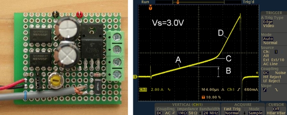
Back to the basics: there are three kinds of passive electronic components: Inductors, Capacitors and Resistors. An inductor can be easily built and many types of core and bobbin kits are available. However, characterizing one hypothetical coil you just made is quite tricky as its inductance will depend on the measurement frequency and DC bias current. That’s why [ChaN] designed the circuit shown above.

As you may guess, RF enthusiasts are more interested in the inductance vs frequency curve while power circuit designers prefer inductance vs load current (for a given frequency). The basic principle behind the circuit shown above is to load an inductor for repetitive short periods and visualizing the current curve with an oscilloscope connected to a sense resistor. When loading the inductor, the current curve will be composed of two consecutive slopes as at a given moment the coil’s core will be saturated. Measuring the slope coefficient then allows us to compute the corresponding inductance.

[Via Dangerous Prototypes]

A Very Professional Homemade CNC Router

[Benne] has a small workshop at home so he decided to make a very versatile CNC router for his final project at school. It took him around 6 months to arrive at the result you can see in the image above and what is even more impressive is that he was only 17 years old at the time.

[Benne] used the free cad program Google Sketchup to draw the different parts he needed around the linear rails and ball screws he already had lying around. The CNC’s travel is 730x650x150mm, uses Nema 23 (3Nm) steppers, 15mm thick aluminum plates and 30x60mm aluminum extrusions. In his article, [Benne] gives great advice to those who would like to design their CNC like his, providing very useful links to manufacturers. He estimated the cost of his CNC to be around 1500 euros (about $2000). We’ll let you browse the many lines of his very detailed build log, which makes us wish to be as talented as him even at our age…

A Much More DYI Air Gap Flash Unit

In reaction to the other air gap flash unit we featured a few days ago, [Eirik] sent us a tip about another one he recently made. In his setup, the duration of the flash peak intensity is around 300ns (1/3,333,333 of a second). As a reminder, an air flash unit consists of a circuit charging a high voltage capacitor, a circuit triggering a discharge on demand, a high voltage capacitor and the air flash tube itself. The flash tube contains two wires which are separated just enough to not spark over at max potential. Isolated from the other two, a third wire is placed in the tube. This wire is connected to a trigger/pulse transformer, which will ionize the gap between the two capacitor leads. This causes the gap to breakdown and a spark to form, thereby creating a flash of light.

[Eirik] constructed his flash tube using an olive jar and a glass test tube. As you can see from the (very nice) picture above, the spark travels along the glass test tube, making the quenching much faster than in an open air spark. [Eirik] built his own high voltage capacitor, using seven rolled capacitors of roughly 2nF each made with duct-tape, tin foil and overhead transparencies. For ‘safety’ they are stored in a PP-pipe. A look at the schematics and overall circuit shown on the website reveals how skilled [Eirik] is, making us think that this is more a nice creation than a hack.

Disclaimer: As with the previous airgap flash, high voltages are used here, so don’t do this at home.

Making An Airgap Flash

[Maurice] and his team just finished the airgap flash they’ve been working on for a year now. This kind of flash is useful for very high speed photography such as photographing shooting bullets. With a duration of about a millionth of a second it is 30 times faster the normal flashes at their fastest settings. In the video embedded after the break, [Maurice] first explains the differences between his flash and a conventional one which normally uses a xenon flash tube, then shows off different photos he made with his build.

Even though this video is a bit commercially oriented, [Maurice] will make another one detailing the insides. In the mean time, you can checkout the schematics in the user manual (PDF) and also have a look at an other write up he made which we covered in the past. We should also mention that trying to make this kind of flash in home is very dangerous as very high voltages are used (in this case, 16kV).

Continue reading “Making An Airgap Flash”

Easy-phi: An Open Source Platform For Experimenters

As a few of Hackaday readers may already know, my day job involves working with high speed electronics. For the last few months, my team at [Université de Genève] in Switzerland has been working on an open source platform (mostly) targeted for experimenters: the easy-phi project. The main idea is to build a simple, cheap but intelligent open hardware/software platform consisting of a 19″ frame (or smaller), which can house a big variety of electronic modules. Hobbyist would therefore only make/buy the modules that would suit their needs and control them through a web page / standalone application / Labview module.

I detailed in more depth on my website the technical aspects of the project. To give you a quick and simple overview, the rack is essentially a USB hub that connects all the modules to a Cubieboard. It also integrates a few synchronization signals, a clock and a monitoring system for voltages, temperatures, power consumption. The modules are made of template + module specific electronics. The template electronics are part of the ‘easy-phi standard’, they consist of the Arduino compatible SAM3X8E microcontroller and of a few other power related components. This ensures electrical and firmware compatibility between the rack and modules that you guys may develop. It is important to note that the modules are enumerated on the USB bus as composite CDC (communication device) and MSC (mass storage). The CDC is used to configure the module while the MSC allows you to grab its documentation, resources, and standalone application in case you use the module without the rack.

The chosen schematics / layout software is Kicad, and all current files can be found on our github. Others will be uploaded once we have tested the other modules currently in the pipe. As the ones we’re developing are physics oriented, we hope that enthusiasts will bring easy-phi to other domains. Don’t hesitate to contact us if you have any question or if you’d like to contribute.

Making A Diode Matrix ROM

Here is a nice project that allows youngsters (but also adults!) to actually see the data stored in a Read Only Memory (ROM). The memory shown in the picture above is made of diodes. [Scott] made it as a part of his Barcamp Fall 2013 presentation about visualizing ROMs. He starts his write-up by stating the obvious: this memory is not practical. Nonetheless, it still was a fun exercise to do. [Scott] then greatly described all the different kinds of read only memories that you can find out there, with a few words explaining how they work. In his diode ROM, bits are ‘programmed’ by adding (or not) a diode between a given data line (anode) and an address line (cathode). When pulling low a given address line, the corresponding data line will only be pulled low if a diode is present. [Scott] finally checked his circuit by using a very old device programmer which could only be run in DOS.

Building A Rail Gun

[Valentin] tipped us about his latest project: a homemade railgun. For the few that may not know already, a railgun is an electrically powered electromagnetic projectile launcher. It is comprised of a pair of parallel conducting rails, along which a sliding armature is accelerated by the electromagnetic effects of a current that flows down one rail, into the armature and then back along the other rail. [Valentin]’s writeup starts with a detailed explanation of this principle, then a simple proof of concept is shown where a metal stick with two small round magnets on each end is accelerated along two alumium strips powered by a 9V battery.

The final build shown above is powered by a capacitor bank consisting of three 400V 2200uF capacitors in parallel. [Valentin] opted for a hot rail design, where the power is always present on the rails. The projectile is inserted into the assembly by a spring-loaded lever. A video is embedded after the break. If you found this interesting, you’re going to love the fully-automatic Gauss gun.

Continue reading “Building A Rail Gun”