Unusual Port Combines DisplayPort And HDMI

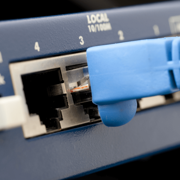
Everyone knows you can’t plug an HDMI cable into a DisplayPort… port, and yet a recent video from [Jon Bringus] challenges that seemingly obvious assumption. The hardware in question is a variant of the 2013-era Xi3 X7A mini PC, code-named ‘Piston’ and also known as a ‘Steambox’, from back when that was still something that Valve was working on. Although the physical format here is definitely quaint, it might be implementing DisplayPort Dual-Mode (DP++), which was introduced around the same time.

With DP++ the DP port can detect when a DVI or HDMI adapter is connected and then transmit DVI/HDMI TMDS signals rather than DP signals. Since DP and HDMI/DVI use a different signaling scheme, normally an active adapter would be required. One disadvantage of DP++ is that the HDMI signal will be limited to e.g. 1920×1080 @ 120 Hz and 4K only at 30 Hz.

Normally a DP++ port is marked as such, and requires an adapter that works with the DP++ port. What Xi3 did in this case to make regular DP and HDMI connectors work seems to be somewhat of a mystery, with any information on this type of port being rather scarce. [Jon] thinks he may have found the part itself listed on Mouser, but isn’t completely sure.

Feel free to leave your thoughts and any information you have on this oddity in the comments.

Continue reading “Unusual Port Combines DisplayPort And HDMI”

Playing ZX Spectrum’s Manic Miner On The Arduino Uno

Composite output shield with audio driver and controller inputs for Arduino Uno (Credit: Scott Porter)

Although it seems many have moved on to 32-bit MCUs these days for projects, there is still a lot of fun to be had in the 8-bit AVR world, as [Scott Porter] demonstrates with a recent Arduino Uno project featuring his game engine running a port of the Manic Miner game that was originally released in 1983 for the ZX Spectrum. For the video and audio output he created an add-on board for the Uno that creates a composite signal using two resistors, along with an audio driver circuit and control inputs either from the onboard buttons or from a NES controller. Audio can be sent either over the composite output or via the audio jack.

A demonstration of the game is provided in a number of videos on [Scott]’s YouTube account, which shows off a few levels, at 256×256 resolution. It contains all 20 original levels, with a few quality of life upgrades with animation. It also features original music, which may or may not work for you, but music can be turned on or off in the main menu. Compared to the 3.5 MHz Z80 MPU in the ZX Spectrum, the 16 MHz AVR of the Uno is a lot beefier, which raises the hope that a color version like the ZX Spectrum one is also in the future, even if it may require an add-on board with a framebuffer. As [Scott] notes, the weakness of the Uno is that the ZX Spectrum has significantly more RAM, which limits what can be done.

Thanks to [256byteram] for the tip.

Continue reading “Playing ZX Spectrum’s Manic Miner On The Arduino Uno”

Reducing Seams In FDM Prints With Scarf Joint Seams

One unavoidable aspect of FDM 3D printing is that each layer consists out of one or more lines that have a beginning and an end. Where these join up, a seam is formed, which can be very noticeable if the same joint exists on successive layers. Taking a hint from woodworking, a possible solution is now being worked on that involves scarf joints. This research is covered by [Michael Laws] in a recent Teaching Tech video on YouTube, where he also details his own printing attempts with a custom 3D model, and a guide by [psiberfunk/Adam L].

The idea for a scarf joint was pitched practically simultaneously by [vgdh] on the PrusaSlicer GitHub, and [Noisyfox] on the OrcaSlicer GitHub. The basic idea follows the woodworking and metalworking version of a scarf joint, with the overlap between two discrete parts across two heavily tapered ends. As with the woodworking version, the FDM scarf joint is not a silver bullet, and with the under development OrcaSlicer builds a lot of the parameters are still being tweaked to optimize the result.

If it can be made to work, it could mean that scarf joints will soon be coming to an OrcaSlicer and PrusaSlicer release near you. Theoretically it should mean faster prints than with randomized seams as fewer print head adjustments are needed, and it may provide a smoother result. Definitely an interesting development that we hope to see come to fruition.

Continue reading “Reducing Seams In FDM Prints With Scarf Joint Seams”

μRepRap: Taking RepRap Down To Micrometer-Level Manufacturing

When the RepRap project was started in 2005 by [Dr Adrian Bowyer], the goal was to develop low-cost 3D printers, capable of printing most of their own components. The project slipped into a bit of a lull by 2016 due to the market being increasingly flooded with affordable FDM printers from a growing assortment of manufacturers. Now it seems that the RepRap project may have found a new impetus, in the form of sub-millimeter level fabrication system called the μRepRap as announced by [Vik Olliver] on the RepRap project blog, with accompanying project page.

The basic technology is based around the OpenFlexure project’s Delta Stage, which allows for very precise positioning of an imaging element, or conceivably a fabrication tool. As a first step, [Vik] upgrade the original delta stage to a much reinforced one that can accept larger NEMA17 stepper motors. This also allows for standard 3D printer electronics to control the system much like an FDM printer, only at much smaller scales and with new types of materials. The current prototype [Vik] made has a claimed step accuracy of 3 µm, with a range of tools and deposition materials being considered, including photosensitive resins.

It should be noted here that although this is a project in its infancy, it has solid foundations due to projects like OpenFlexure. Will μRepRap kickstart micrometer-level manufacturing like FDM 3D printing before? As an R&D project it doesn’t come with guarantees, but color us excited.

Thanks to [Tequin] for the tip.

Fastest FPV drone, pending official confirmation. (Credit: Luke Maximo Bell)

Got To Go Fast: The Rise Of Super-Fast FPV Drones

Generally when one considers quadcopter drones, the term ‘fast’ doesn’t come to mind, but with the rise of FPV  (First Person View) drones, they have increasingly been designed to go as fast as possible. This can be for competitive reasons, to dodge enemy fire on a battlefield, or in the case of [Luke Maximo Bell] to break the world speed record. Over the course of months he set out to design the fastest FPV drone, involving multiple prototypes, many test runs and one failed official speed run.

The components of the third FPV drone attempt, as used with the world record attempt. (Credit: Luke Maximo Bell)

The basic design of these designed-for-speed FPV drones is more reminiscent of a rocket than a quadcopter, with the upside-down propellers  requiring the operator first lifting the drone into the air from an elevated position. After this the drone transitions into a level flight profile by rotating with the propellers pointing to the back. This gives the maximum thrust, while the body provides lift.

Although this seems simple, flying this type of drone is very hard, as it’s hard to tell what is happening, even when landing. [Luke] ended up installing a camera in the nose which can rotate to provide him with different angles. Tweaking the flight computer to deal with the control issues that occur at speeds above 300 km/h.

Continue reading “Got To Go Fast: The Rise Of Super-Fast FPV Drones”

How Thermal Post-Curing Resin Prints Affects Their Strength

Tensile strength of resin parts. (Credit: CNC Kitchen)
Credit: CNC Kitchen

Resin 3D prints have a reputation for being brittle, but [Stefan] over at [CNC Kitchen] would like to dispel this myth with the thing which we all love: colorful bar graphs backed up by scientifically appropriate experiments. As he rightfully points out, the average resin printer user will just cure a print by putting it in the sunshine or in a curing station that rotates the part in front of some UV lights. This theoretically should cause these photosensitive resins to fully cure, but as the referenced Formlabs documentation and their Form Cure station indicate, there’s definitely a thermal element to it as well.

To test the impact of temperature during the UV curing process, the test parts were put into an oven along with the UV lamp. Following this uncured, ambient cured and parts cured at 40 to 80 ºC were exposed to both tensile strength tests as well as impact strength. The best results came from the Siraya Tech Blu resin cured at 80 ºC, with it even giving FDM-printed parts a run for their money, as the following graphs make clear. This shows the value of thermal post-curing, as it anneals the resin prints. This reduces their impact strength somewhat, but massively improves their tensile strength.

Continue reading “How Thermal Post-Curing Resin Prints Affects Their Strength”

2D Plotter attachment for 3D printer.

Ender 3 Plotter Attachment For Printing Onto Cassettes

One way to look at FDM 3D printers is as machines that turn filament into three-dimensional objects, but at their core they are much more versatile than that. Since they can move just about any tool around in 3D space, you can also use them for plotter tasks, a fact that [Geoffrey Gao] made use of when he had to write labels for a stack of music tapes. The resulting FS-Plotter project is based around a Creality Ender 3 FDM printer. Standard g-code from PrusaSlicer is used to move a pen around, after the latter has been fitted into a (3D-printed) spring-loaded fixture.

The cassette tape is fitted into its own fixture that is attached to the printer bed to hold it in place, while the writing utensil can move in its spring-loaded fixture to account for some unevenness on the surface it’s writing on. In the linked GitHub project a PrusaSlicer profile is provided that can generate 2D plotter Gcode. Where [Geoffrey] says that this project is very useful to him as a musician is that it enables him to make small runs of tapes with professional printing, without running into extra expenses.

Beyond putting a writing utensil into the holder, it could also be used for light engraving and similar tasks, while still making it possible to switch between the FDM hotend and this plotter attachment as needed. For about $30 in parts, it doesn’t seem like a bad deal to get a small-ish plotter and maybe give that old Ender 3 a second life.