Cellphone Charger Has A USB Port Forced Upon It

We still can’t figure out why a standard charging scheme hasn’t been developed for handheld devices (other than greed). Certainly we understand that many devices have different electrical needs as far as voltage and current are concerned, but we still long for the ability to use one charger for many different doodads. [Rupin] is trying to narrow down the number of dedicated chargers he uses by adding a USB charging port to his Nokia cellphone charger. Since the USB standard calls for regulated 5V a hack like this can often be done just by patching into the power output coming off of the voltage regulator in the plug housing of the device. [Rupin’s] charger had 5V printed on the case, but when he probed the output he found well over 8 volts. He added a 7805 linear regulator to get the stable output he needed, then cut a hole in the case to house the connector.

Since [Rupin] wants to use this as an iPod charger he couldn’t just let the two data lines float. Apple uses a specific charger verification scheme which requires some voltage dividers to get the device to start charging.

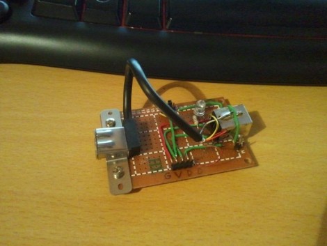
USB Man-in-the-middle Adapter

The module works as a pass through, providing access to data and power lines for a USB device. [BadWolf] built it in order to sniff out communications between peripherals and the Universal Serial Bus. For now it just provides access to the different signals, but we think there’s quite a bit of usefulness in that. First off, the power rail is mapped out to a jumper, making it dead simple to monitor the voltage stability or patch in a multimeter to get feedback on current consumption. But you can also see in the foreground that a pin socket makes it easy to tap into the board using jumper wires. We think it would be a great breadboard adapter for USB work that would continue being useful after you’ve populated your first PCB for the prototype.

[BadWolf] has other plans in store for it though. He wants to intercept and decipher the communications happening on the data lines. In the video after the break he mentions the possibility of using a Bus Pirate for this (we have our doubts about that) but plans to start his testing with an STM32 discovery kit. We can’t wait to see what he comes up with.

Tokyo Hackerspace Helping Disaster Victims

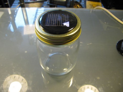
We, like the rest of the world, have watched in horror as footage of the recent earthquake-caused disaster has been reported from northern Japan. It’s easy to watch video and see nothing but distruction, however, life goes on and [Akiba] is looking for a way to help the recovery efforts. He mentions that one of the big needs in the disaster area right now is for light, as the power infrastructure has been heavily damaged. The mason jar seen above is a Kimono Lantern that was meant to accent a garden at night. It has a solar cell – one NiMH rechargeable battery – and one bright LED along with a charging circuit. It was designed in the Tokyo Hackerspace and they released the build files in hopes that a large number can be donated to those in need. With a reasonable amount of daylight, the single cell battery can be charged enough to provide 10 hours of light from the little device.

How can our hacks help others? That question has been on our minds for the last few days. Light is a great first step. But we’ve also wondered about information networks to help coordinate rescue and cleanup workers. There are hacks that bring WiFi using wind power or solar power. What other hacks do you think would be useful to aid in the recovery process?

PICAXE Using LEDs To Communicate

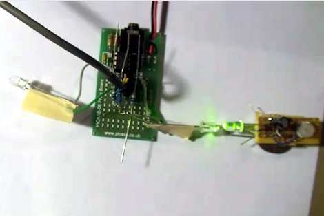
[Relwin] has being working on using LEDs as bi-directional devices. The setup above allows him to use each LED as an input, looking for a bright light source and then syncing up with the activity it receives. It is the most basic of communications using the components. The hardware at the heart of the system is a PICAXE development board on the left. The blinking light to the right causes the LED on the left of the picture to blink, but moving the blinking source over to that side will reverse the effect. The chip is programmed to play a tune on a piezo buzzer whenever a connection is lost. What is interesting to us is that these green LEDs will not detect a red LED flashing because the voltage threshold is different on the detector side of things.

He’s got some code available, but we’re really looking for the ideas of what to do with this concept. Maybe something along the lines of LED matrix video puzzles, or a variation on this laser-pointer LED game. Watch the demo video after the break and then let us know what you would use it for by leaving a comment.

Continue reading “PICAXE Using LEDs To Communicate”

Tilt And Pivot Camera Base Uses Just Two Servos

[Caled] shows us how to build a tilt and pivot camera base. One of these can be quite handy for taking precisely aligned images that can later be stitched together into panoramic, or even spherical images. We have grand visions of being able to produce something along the lines of these stunning interactive images with hardware that is cheaper and easier to build than this other motorized rig.

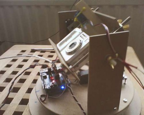
The design utilizes just two servo motors. In the image above you can just make out a pair of discs that serve as the base for the rig. In the center of the upper disc is the first servo, pointing downward, which rotates the camera. Two upright supports on either side of the point-and-shoot provide the framework for the tilt feature. The camera is mounted in a frame whose center is a threaded rod on the near side, and the second servo motor on the far side. An Arduino with a servo shield controls the movements along with a button pad and LCD screen as a user interface. The last step in the project log points to software options for combining the captured photos.

PIC Based Frequency Counter

Here’s a PIC based frequency counter that outputs the count via an RS232 serial connection. [Oakkar7] tipped us off about it after seeing the AVR based counter we featured yesterday. This project is a bit older and a bit dirtier.

Inside the metal DB9 housing you’ll find just seven parts. The most important is a PIC 16F628 which handles both the counting and the serial communications. We’re not quite sure how it’s managing to talk to that USB-to-Serial converter without some type of level conversion. Since this microcontroller is not a dedicated counter chip a little bit of trimming must be done to bring the accuracy into spec. There’s also some physical trimming involved. In order to get everything to fit into the small enclosure the circuit was free-formed without a PCB or protoboard and the case of the DIP chip had to be ground down just a bit. As for the readout, a simple script can grab the data and display it in a terminal.

[via Piclist]

CO2 Powered Pinewood Derby Car Is Definitely Cheating

The Pinewood Derby is a classic Cub Scout competition where dads and sons come together to build a small-scale race car. You start with a kit that includes a block of wood for the body, as well as four plastic wheels and four nails to act as axles. Most innovations in the ‘sport’ center around reducing friction between the wheels and the axles, and making the body as aerodynamic as possible.

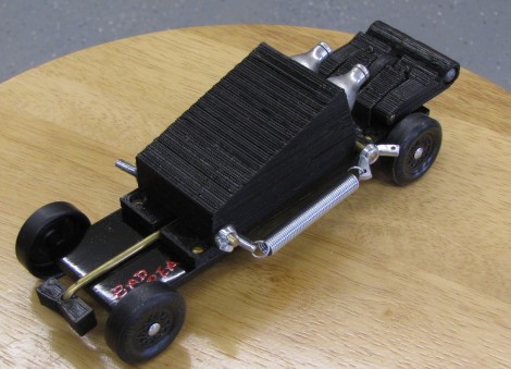
This year [Sliptronic] grabbed an extra kit and threw the rules out the window by powering the car with compressed carbon dioxide. He used a 3D printer to make a housing for two CO2 cartridges that mounts on the center of the chassis. An official Pinewood Derby race track is on an incline and has a wooden gate that keeps each car in place until it is dropped to start the race. [Sliptronic] is using this gate as the triggering mechanism. Springs on either side of the car pull against an arm at the back of the vehicle. This arm is held in place by a rod protruding out the front of the vehicle. When the start gate is dropped that rod releases the trigger, which is pulled up by the springs to pierce the CO2 cartridges. You can see an overview of how that mechanism works in the video after the break.

Continue reading “CO2 Powered Pinewood Derby Car Is Definitely Cheating”