RomoCart, Indoor Robot Racing

Your Living Room Becomes Next Mario Kart Course

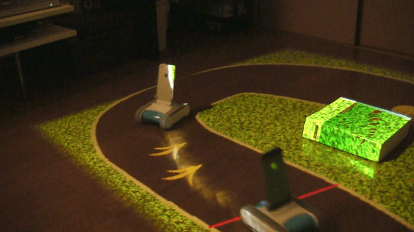
[Ken] likes his living room and he is on a continual mission to make it more interesting. Recently, he has made a giant leap forward with a racing game project he calls RomoCart. Think of it as a partially-physical game of Mario Kart. You are able to race others around a track while still having the ability to fire projectiles or drop defensive measures in efforts to win the race!

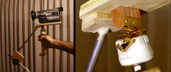
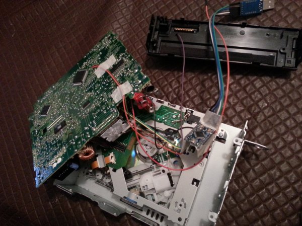
First, lets talk about the hardware required. The racers are standard Romo educational robots. Wireless game controllers provide the means for the drivers to control the Romos. Hanging from the ceiling is an Xtion motion sensing camera and a video projector, both pointed down at the floor.

To get started, the system scans the floor and determines a race course based on the room layout and any physical objects in the vicinity. A course is then generated to avoid the obstacles and is projected onto the floor. At this point it would still be a pretty neat project but [Ken] went way further. The ceiling-mounted camera tracks the motion of the Romos driving around the track and the video projector displays a smoke trail behind each racer. Randomly displayed on the track are items to help you win the race, including an acceleration item that makes your Romo go twice as fast for a short time.

Have a tailgater? No problem, just pick up some bananas and drop them on the track. If a following competitor drives into one, they spin out. If you want to get super rude, pick up some missiles and fire them at the racers ahead of you. A direct hit will stop them right in their tracks.

[Ken] is no stranger to HaD, he’s had a few of his projects covered here before. Check out his Tempescope, Moving Window and his Autonomous Lighting System.

Check out a video of the racing in action after the break. It is amazing!

Continue reading “Your Living Room Becomes Next Mario Kart Course”

DIY Camera Stabilizer

DIY Camera Stabilizer Takes The Shakes Out Of Filming

We’ve all prematurely stopped watching some Youtube video because of shaky camera work that makes the video unwatchable. There is a solution available for this problem, it’s a device called a camera stabilizer and it is designed to compensate for jerky camera movement. There are several types available for purchase but they can get fairly expensive. Even the cheaper ones at a few hundred dollars are not economical for hobbyists. [John] set out to make his own camera stabilizer using some unorthodox parts.

[John’s] chose a gimble style design that effectively lowers the camera’s center of gravity down close to the camera persons hand. The handle of the device must also be mounted in a manor to prevent angular and rotation movement of the supporting hand from transferring to the camera.

The handle is from a cement trowel, on top of which is a ball bearing mounted to a threaded rod. A PVC fitting was heated to soften it and the bushing pressed in. This bearing is responsible for allowing the rotational freedom between the handle and the camera. To decouple any angular movements, two hinges were attached to the PVC fitting. The hinges are perpendicular to each other, one allows forward-back tilting while the other allows left-right tilting. The upper hinge is attached to a piece of poplar wood that also serves as a base for the camera.

At this point, if you were to try to hold this contraption with the camera installed, it would immediately tip over due to gravity. To prevent this, the center of gravity of the moving parts (including the camera) must be lowered. [John] did this by using some aluminum tubing to support wood weights that reside lower than the pivot points created by the hinges.

If you like the DIYer-style stabilizers, check this other wooded one out. Want something more polished looking? How about this pistol grip stabilizer?

CNC Sound Enclosure for Living Room

Sound Isolation Box Makes Living Room Based CNC Routing Tolerable

CNC Machines can be loud, especially if they are equipped with a high-speed router spindle. Unfortunately, such a loud racket could be a problem for the apartment dwellers out there. Fear Not! [Petteri] has come up with a solution. It’s a sound isolation enclosure for his mini CNC Router that doubles as furniture. It keeps the sound and dust in while pumping out some cool parts….. in his living room.

What may just look like a box with an upholstered top actually had a lot of thought put into the design. The front MDF panel folds down to lay flat on the floor so that the user can kneel on it to access the machine without putting unnecessary stress on the door hinges. The top also is hinged to allow some top-down access or permit a quick peek on the status of a job. All of the internal corners of the box were caulked to be air tight, even a little air passageway would allow sound and dust to escape. Two-centimeter thick sound insulation lines the entire interior of the box and the two access lids have rubber sealing strips to ensure an air tight seal when closed.

With stepper motors, the spindle motor and control electronics all running inside an enclosed box, there is some concern over heat build up. [Petteri] hasn’t had any problems with that so far but he still installed an over-temp power cutoff made from a GFCI outlet and a thermostat temperature switch. This unit will cut the mains power if the temperature gets over 50º C by intentionally tripping the GFCI outlet. None of the internal parts will ignite under 300º C, so there is quite a safety buffer.

Although the isolation box came out pretty good, [Petteri] admits there is room for improvement; when cutting wood or aluminum, the noise level is kind of annoying. If he had to do it again, he would use thicker MDF, 20mm instead of 5mm. However, during general use while cutting plastic, the router is still quieter than his dishwasher.

Video below.

Continue reading “Sound Isolation Box Makes Living Room Based CNC Routing Tolerable”

DIY Steering Wheel Control Adapter

Arduino Translates Signals Between Steering Wheel Buttons And Aftermarket Head Unit

There is no question that steering wheel mounted controls are super convenient. Reaching all the way over to the dashboard to change a radio station is so 1990’s. An ever-increasing percentage of new cars are coming equipped with steering wheel controls for the stereo, however, you’ll lose the button control if you change out the stock head unit to something a little higher in quality. Sure, there may be an adapter readily available for your car/stereo combination, but there also may not be. [Ronnied] took the DIY road and made his own adapter.

The first obstacle for [Ronnied] was to figure out the wiring on the steering wheel controls. After some poking around he found that there were only two wires used for all of the control buttons, each button only changing the resistance between the two wires. The button states could easily be read by using an Arduino’s analog input. A Pro Mini model was chosen for its small size as it could be housed in the radio compartment of the dash.

The next step was getting the Arduino to control the aftermarket head unit. [Ronnied] did some research regarding JVC’s Stalk digital control interface but came to the conclusion that it would be easier to direct wiring the Arduino outputs to the appropriate spot on the head unit’s circuit board. To do this the button for each function that would also be represented on the steering wheel was traced out to find a common point on the circuit board. Jumper wires soldered to the circuit board simply allow the Arduino to emulate button pushes. To ensure that the head unit buttons still work in conjunction with the steering wheel buttons, the Arduino would have to keep the pins as inputs until a steering wheel button was pushed, the pin changed to an output, the signal sent and the pin changed back to an input. This feature was easily created in the Arduino sketch.

Video below.

Continue reading “Arduino Translates Signals Between Steering Wheel Buttons And Aftermarket Head Unit”

Neat DIY Valve for watering system

Automated Watering System Uses Neat DIY Water Valve

[Valentin] is an engineering student and hobbyist gardener. He was planning on going home for a 3 week semester break and certainly could not leave his balcony plants to fend for themselves. The clearly obvious solution was to make an automated watering system!

The most interesting part of this build is the valve. Anyone could have bought an off-the-shelf solenoid valve, not [Valentin], he designed his own. It is simple and just pinches the water supply tube to stop the flow of water coming from the elevated 20-liter water container. The ‘pinching’ arm is raised and lowered by an RC Car servo. When the valve is in the closed position, the servo does not need to continually apply pressure, the servo is powered down and the valve stays closed. This works because when the valve is closed, all forces are acting in a strictly radial direction on the servo’s drive disk. Since there is no rotation force, the drive disk does not rotate and the valve stays closed.

The servo is controlled by a microcontroller. Instead of rotating the servo to a certain degree, the servo rotates until it hits a limit switch. Those limit switches tell the microcontroller that the valve is either in the open or closed position. You must be asking yourself ‘what happens if the limit switch fails and the servo wants to keep rotating?’ [Valentin] thought of that too and has his code measure how long it is taking to reach the limit switch. If that time takes too long, the servo is powered down.

Video below.

Continue reading “Automated Watering System Uses Neat DIY Water Valve”

DIY Lathe DRO

Digital Caliper Sacrificed For DRO Project

In general, machining metal on a lathe or mill takes skill and patience as the accuracy of the cuts are important. To make those accurate cuts, it is important to know where the tool is located and how far it moves. For manual machines, the most basic method of determining position is by using graduated dials mounted on the hand cranks. Although these graduated dials can certainly be accurate, they may be difficult to see and they also require the operator to do math in their head on the fly with every full revolution of the dial. Another option would be a digital read out (DRO) which has an encoder mounted to the moving axes of the machine. This setup displays the exact position of the tool on an easy to read numeric display.

Professional DRO kits for mills and lathes can cost between a few hundred dollars to several thousand dollars.  [Robert] has a lathe, wanted a DRO but didn’t want to shell out serious cash to get it. He built his own for super cheap in an extremely resourceful way…. using a Harbor Freight Digital Caliper. A housing was first fabricated so that the added equipment would not hinder the axis travel of the lathe. The caliper was then cut to length, installed in the housing and the entire assembly was then mounted to the lathe.

DIY Lathe DRO
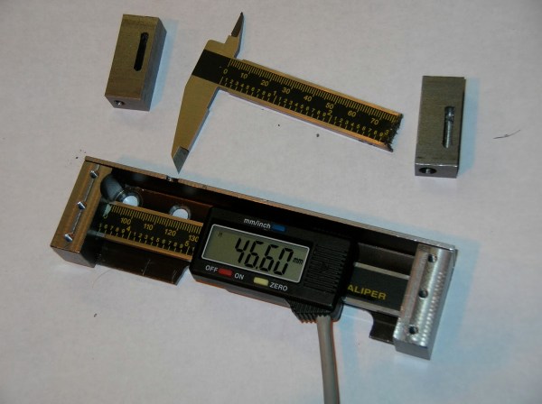
It is totally reasonable to use the stock caliper display to read the positional information, however, even these cheap digital calipers have connections for the encoder output data, which can easily be read by a microcontroller. That means it is super simple to hook these low-cost digital calipers up to a display remotely located in a more convenient position.


DIY Electro Magnetic Pulser

EM Pulser Flings Washers, Side Effects May Include Curing Cancer Or Death

Some folks believe that exposure to electromagnetic pulses helps the human body heal itself (one portion of the [Bob Beck] protocol). [Steffan] is one of those folks and was interested in EMP generation but wasn’t crazy about the several-hundred dollar price tag for professional units. As any determined DIYer would do, he set off to make his own.

This whole thing works by straight-out-of-the-wall 110v AC running through a couple 60 watt light bulbs before moving through a rudimentary rectifier circuit. The DC output from the rectifier charges five 130uF camera flash capacitors. An inductor coil is responsible for generating the EMP and is only separated from the capacitors by a single normally-open momentary switch. Although it is possible to wrap your own coil, [Steffan] decided to use an off the shelf 2.5mH unit normally used for speaker system crossovers. Once the momentary switch is pressed, the energy in the capacitors is discharged through the inductor coil and the EMP is created. To demonstrate that the pulser does indeed work, a metal washer was placed on the inductor coil and the unit fired resulting in the washer being thrown into the air.

[Stephan] did deviate from the some of the online designs he had researched, using 7 capacitors instead of the recommended 5. The result was a firecracker-like discharge sound and melting of the 14 gauge wire. Well, back to 5 caps.