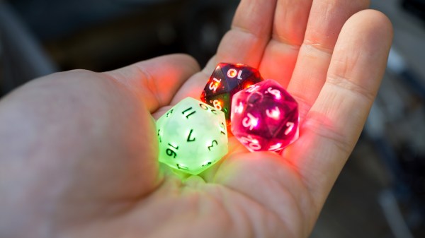
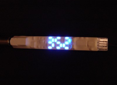
Fans of D&D are surely aware of the significance of a good pair of dice. What if your dice were not only stylish, but smart? For anyone who’s ever had to deal with playing board games with less than reputable siblings or friends, the electric die just might be your savior.
The dice are configured via Bluetooth, tracking rolls and stats over the course of gameplay captured by an accelerometer.
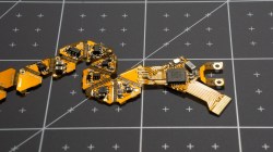
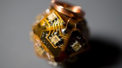
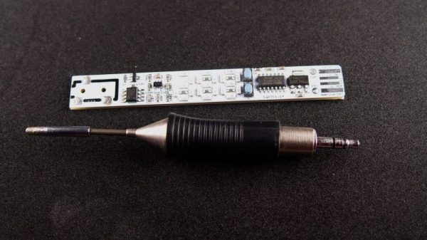
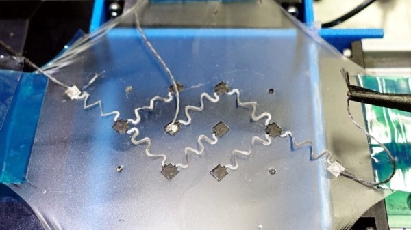
The PCB had to have a flexible surface – specifically in the shape of an unfolded icosahedron – in order to form the shape of the die which constrains the design to two layers. Each face contains an LED facing outwards to light up the number on that side. The LEDs are directly powered by a rechargeable battery, which uses a small coil for wireless inductive charging. Rather than opting for a Qi charger chipset, which regulates the maximum amount of power transmitted if the efficiency falls below a threshold, [Jean Simonet] uses a simpler charger setup using a full bridge rectifier, capacitors, and a linear regulator to create a stable 5V supply for the receiving end.
While the initial design for the die required an injection molded plastic shell, an easier solution was to simply cast the designs in resin. The electronics are placed into a dice mold and cast just as a regular die would be.
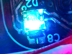
This luckily also solved the issue of needing to fit the components inside a screw-on container with a removable lid, which presented a hassle in terms of finding a battery that would fit the dimensions. The LEDs – purchased for cheap on Alibaba – are daisy chained to reduce the complexity of the routing.
One issue with the LEDs, however, is that the internal PWMs modulating the intensity remain on even at an intensity of 0, constantly drawing 21 mA (for the 21 LEDs on the die). This causes the battery to die after 2-3 hours. The solution [Simonet] used was to add a transistor to cut off power to the LEDs and to have the MCU toggle the transistor when the LEDs are turned off. Even this solution didn’t solve the entire problem since the LEDs still drain current from the data and clock lines, so those lines had to be low before going to sleep.
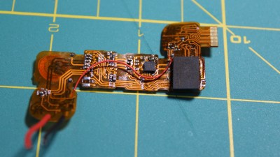
There were some stability issues with using a small buck converter to bring the LiPo voltage down to 3.3V, so the power regulation was done directly by the MCU instead. Switching the die off is controlled by a magnetic switch connected to a power buck converter that turns off logic when a magnet is present. This initially caused the LED control lines to become floating when power was turned off, turning the LEDs to arbitrary colors. The solution was to wire the output of the magnetic sensor to the MCU and to allow the software to handle the LEDs as well.
Maybe it’s because creator [Simonet] happens to be a game developer as well, but the early development stages of the electronic die (CAD, circuit schematics, prototyping, hand soldering components) were streamed on Twitch, adding some interactivity to even the build phase. The end result may be small, but these dice certainly have large brains!

