You may not have noticed, but so-called “artificial intelligence” is slightly controversial in the arts world. Illustrators, graphics artists, visual effects (VFX) professionals — anybody who pushes pixels around are the sort of people you’d expect to hate and fear the machines that trained on stolen work to replace them. So, when we heard in a recent video that [Niko] of Corridor Digital had released an AI VFX tool, we were interested. What does it look like when the artist is the one coding the AI?
It looks amazing, both visually and conceptually. Conceptually, because it takes one of the most annoying parts of the VFX pipeline — cleaning up chroma key footage — and automates it so the artists in front of the screen can get to the fun parts of the job. That’s exactly what a tool should do: not do the job for them, but enable them to enjoy doing it, or do it better. It looks amazing visually, because as you can see in the embedded video, it works very, very well.
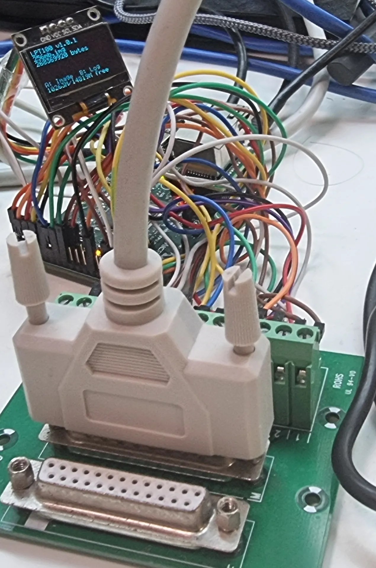
Iomega’s Zip drives filled an interesting niche back in the 1990s. A magnetic disk that was physically floppy-sized, but much larger in capacity– starting at 100 MB, and reaching 750 MB by the end–they never quite had universal appeal, but never really went away until flash memory chased them out of the marketplace in the early 2000s. While not everyone is going to miss them, some of us still think it’s a better form factor than having a USB stick awkwardly protruding from a computer, or microSD cards that are barely large enough to see with the naked eye. [Minh Danh] is one of those who still has affection for Zip drives, and when his parallel port Zip 100 drive started to give up the ghost last year, he decided to do something bold: reverse engineer it, and produce an emulator. First software, and then in hardware.
It’s not the prettiest-ever prototype, but lots of great things start with a mess of wires.
The first was to create a virtual zip drive that could run on a virtual machine and be accessed with DOS or Windows up to XP. The next task was to move that functionality onto a microcontroller to create something like a GoTek floppy emulator for LPT Zip drives that he’s calling the LPT100. Yes, Zip drives were built for ATAPI, SCSI, FireWire and USB, too, but [Minh]’s was on the parallel port and that’s what he wanted to replace, so the LPT interface is what set out to recreate.
It works, too, though took more guts than was expected– the 8-bit PIC18F4680 he started with just wasn’t up to the task. He moved up to a 32-bit PIC, the PIC32MZ2048EFH144 to be specific, which proved adaquate when testing with his Book 8088, a new DOS PC from 2023. Iomega’s official driver won’t run on an 8088, but the PALMZIP utility does and was able to transfer files, though only at the slow nibble rate due to limitations with the Book8088’s LPT hardware. Watch it in action below.
Alas, moving up to the Pocket386, it seemed the PIC just could not keep up. [Minh] says he’s thinking of moving to the faster Teensy 4.1, which sounds like a good idea. Considering the Teensy can be configured to serve as a drop-in replacement for a 68000, bit-banging the bus at 7.8 MHz, we’d think it should handle anything a parallel port can throw at it.
Full-color 3D printing is something of a holy grail, if nothing else, just because of how much it impresses the normies. We’ve seen a lot of multi-material units in the past few years, and with Snapmaker’s U1 and the Prusa XL, it looks like tool changers are coming back into vogue. Just in time, [Ratdoux] has a fork of OrcaSlicer called FullSpectrum that brings HueForge-like color mixing to tool-changing printers.
The hook behind FullSpectrum is very simple: stacking thin layers of colors, preferably with semi-translucent filament, allows for a surprising degree of mixing. The towers in the image above have only three colors: red, blue, and yellow. It’s not literally full-spectrum, but you can generate surprisingly large palettes this way. You aren’t limited to single-layer mixes, either: A-A-B repeats, and even arbitrary patterns of four colors are possible, assuming you have a four-head tool-changing printer like the Snapmaker U1 this is being developed for.
FullSpectrum is, in fact, a fork of Snapmaker’s fork of OrcaSlicer, which is itself forked from Bambu Slicer, which forked off of PrusaSlicer, which originated as a fork of Slic3r. Some complain about the open-source chaos of endless forking, but you can see in that chain how much innovation it gets us — including this technique of color mixing by alternating layers.
Anyone who saw Back to the Future II was disappointed when 2015 rolled around with nary a hoverboard in sight. There have been various attempts to fake it, but none of them quite have the feel of floating about wherever you’d like to go that the movie conveys. The little-known YouTuber [Colin Furze] has a new take on the idea: use magnets. Really big magnets.
If you’re one of [Colin]’s handful of subscribers, then you probably saw his magnetic-suspension bike. We passed on that one, but we couldn’t resist the urge to cover the hoverboard version, regardless of how popular [Colin] might be on YouTube. It’s actually stupidly simple: the suspension is provided by the repulsive force between alarmingly large neodymium magnets. In this case, two are on the base plate that holds the skateboard ‘trucks’, and two are on the wooden ‘deck’ that [Colin] rides upon.
Of course magnetic repulsion is a very unstable equilibrium, so [Colin] had to reduce the degrees of freedom. In his first test, that was with a pair of rods and linear bearings. That way the deck could only move in the z-axis, providing the sensation of hovering without allowing the deck to slide off its magnetic perch. Unfortunately those pins transferred too much vibration from the ground into the deck, ruining the illusion of floating on air.
Platinum-group metals (PGMs) are great catalysts, but they’re also great investments — in the sense that they are very, very expensive. Just ask the guy nicking car exhausts in the Walmart parking lot. If one could replace PGMs with a more common element, like, say the aluminum that makes up over 8% the mass of this planet, it would be a boon to the chemical industry, and a bane to meth addicts. Researchers at King’s College, London have found a way to do just that, with a novel form of aluminum called cyclotrialumane.
The aluminum trimer is exactly what the ‘tri’ in the name makes it sound like: three aluminum atoms, bonded in a triangular structure that is just pointy and stick-outy enough to poke into other molecules and make chemistry happen. OK, not really — you can see from the diagram above it’s not nearly that simple — but the point is that the shape makes it a good catalyst. The trimer structure is useful in large part because it is very stable, allowing reactions to be catalyzed in a large variety of solutions.
The researchers specifically call out their trialuminum compound as effective at splitting H2 in to H+ ions, as well as ethene polymerization. Both of those are important industrial reactions, but that’s only a start for this trialuminum wonder catalyst, because the researchers claim it can catalyze totally new reactions and create previously-unknown chemicals.
If you never took chemistry, or it’s been too many years since you last slept through that class, we have a primer on catalysts here. By accelerating chemical reactions, catalysts have enabled some neat hacks, like anything involving platinum-cure silicone.
Thanks to [Lightislight] for the tip! Hacks do appear here on their own, but you can always use our tips line to catalyze the synthesis of a particular article.
Header image adapted from: Squire, I., de Vere-Tucker, M., Tritto, M. et al. A neutral cyclic aluminium (I) trimer. Nat Commun17, 1732 (2026). https://doi.org/10.1038/s41467-026-68432-1
If you weren’t around for the early PC era, or were a little more casual about operating systems, you could perhaps be forgiven for not knowing that DOS is not synonymous with MS-DOS. MS-DOS was just Microsoft’s implementation — or rather, an implementation they purchased — of a Disk Operating System, one that was…let’s just say “inspired by” Digital Research’s CP/M.
Digital Research shot back with DR-DOS, an operating system that was both compatible with and much superior in some ways to MS-DOS. The last version was released in 1991, after Novell bought the struggling Digital Research. Now it’s back, or at least, it’s on its way back with a fully clean-room implementation by a fellow who calls himself [CheeseWeezel] on Reddit.
He’s gone so far as to purchase the trademark, so this re-creation is the official DR-DOS. In any case [CheeseWeezel]’s DR-DOS is considered version 9.0, and is currently in Beta. The clean-sheet re-implementation of DR-DOS’s API was sadly necessary due to the rather tortured history of the IP after DR was bought by Novel, who sold DR-DOS to Caldera, who briefly open-sourced the code before retracting the license and selling on. Some of you may remember a controversy where a previous rights holder, DR DOS INC, was found purloining FreeDOS code in violation of the GPL. Perhaps because of that, [CheeseWeezel] isn’t using any old code, and isn’t open-sourcing what he’s done. Right now, the beta of DR-DOS 9 is free for non-commercial use, but as is standard for EULAs, that could change at any time without warning. [CheeseWeezel] is still working full compatibility, but at this point it at least runs DOOM.
Still, given the origins of DOS in Digital Research’s early work on CP/M, it warms the heart to see what many of us thought of as the “true” DOS survive in some form in the 21st century. Arguably it already had, in the form of SvarDOS, but you can’t use that to make smug jokes about your operating system having PhD instead of a measly master’s. If you did not like DOS, we recall the joke from Mac users was that those were the degrees needed to operate the PC. Speaking of DOS, you don’t necessarily need a retrocomputer to run it.
[My Engines] has been doing some sterling work on Stirling engines for some years now. Their thermoacoustic engine is now finally far enough along to open-source, so the magic of collaboration can speed technological advancement.
You’ve probably heard of Stirling Engines, but what’s this “thermoacoustic” business? Hot sound? Well, that’s the translation, and it’s not a bad starting point for understanding what’s going on: the engine converts heat into high-amplitude sound waves — that is, waves of pressure — which means the engine itself has no moving parts. Well, almost. Obviously moving parts are required to get power out. In [My Engines] case he’s using a piston and linear generator, but otherwise it makes for a very simple, very reliable engine that can be fueled by any available source of heat. Say like burning methane from [My Engines]’s home biogas plant.
[My Engines] promises more videos to help you understand the construction in a way his previous videos might not detail, and has put 3D models and drawings at a public Google Drive. There’s also a Discord you can join, because apparently that’s the only way to communicate about projects these days.
The whole build is very much within range of a home maker, though there’s a lot more to it than the toy Stirling engines you may have made out of tin cans back in the day. If you want to play with thermoacoustics but [My Engines]’s design seems like a little much to get started with, you can make a demonstrator with some steel wool and a test tube. Be careful, though: model engines can be an addictive hobby.