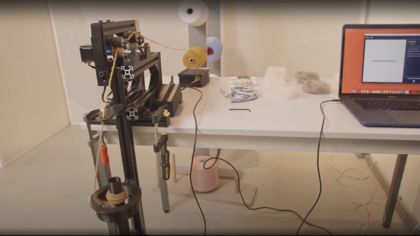
open hardware textile spinning machine constructed from aluminium extrusions, arduino electronics and 3D printed parts

An Open Hardware Automatic Spinning Machine

The team at the Berlin-based Studio HILO has been working on ideas and tools around developing a more open approach to small-scale textile production environments. Leveraging open-source platforms and tools, the team has come up with a simple open hardware spinning machine that can be used for interactive yarn production, right on the desktop. The frame is built with 3030 profile aluminium extrusions, with a handful of 3D printed, and a smidge of laser cut parts. Motion is thanks to, you guessed it, NEMA 17 stepper motors and the once ubiquitous Arduino Mega 2560 plus RAMPS 1.4 combination that many people will be very familiar with.

The project really shines on the documentation side of things, with the project GitLab positively dripping with well-organised information. One minor niggle is that you’ll need access to a polyjet or very accurate multi-material 3D printer to run off the drive wheel and the associated trailing wheel. We’re sure there’s a simple enough way to do it without those tools, for those sufficiently motivated.

We liked the use of Arduino for the firmware, keeping things simple, and in the same vein, Processing for the user interface. That makes sending values from the on-screen slider controls over the USB a piece of cake. Processing doesn’t seem to pop up on these pages too often, which is a shame as it’s a great tool to have at one’s disposal. On the subject of the user interface, it looks like for now only basic parameters can be tweaked on the fly, with some more subtle parameters needing fixing at firmware compilation time. With a bit more time, we’re sure the project will flesh out a bit more, and that area will be improved.

Of course, if you only have raw fibers, that are not appropriately aligned, you need a carder, like this one maybe?

Continue reading “An Open Hardware Automatic Spinning Machine”

Debugging With Serial Print At 5333333 Baud

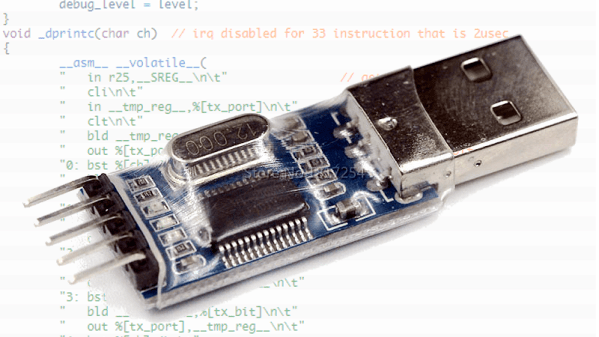
Debugging with printf is something [StorePeter] has always found super handy, and as a result he’s always been interested in tweaking the process for improvements. This kind of debugging usually has microcontrollers sending messages over a serial port, but in embedded development there isn’t always a hardware UART, or it might already be in use. His preferred method of avoiding those problems is to use a USB to Serial adapter and bit-bang the serial on the microcontroller side. It was during this process that it occurred to [StorePeter] that there was a lot of streamlining he could be doing, and thanks to serial terminal programs that support arbitrary baud rates, he’s reliably sending debug messages over serial at 5.3 Mbit/sec, or 5333333 Baud. His code is available for download from his site, and works perfectly in the Arduino IDE.

The whole thing consists of some simple, easily ported code to implement a bare minimum bit-banged serial communication. This is output only, no feedback, and timing consists of just sending bits as quickly as the CPU can handle, leaving it up to the USB Serial adapter and rest of the world to handle whatever that speed turns out to be. On a 16 MHz AVR, transmitting one bit can be done in three instructions, which comes out to about 5333333 baud or roughly 5.3 Mbit/sec. Set a terminal program to 5333333 baud, and you can get a “Hello world” in about 20 microseconds compared to 1 millisecond at 115200 baud.

He’s got additional tips on using serial print debugging as a process, and he’s done a followup where he stress-tests the reliability of a 5.3 MBit/sec serial stream from an ATMega2560 at 16 MHz in his 3D printer, and found no missed packets. That certainly covers using printf as a debugger, so how about a method of using the debugger as printf?

The King Of All Game Genies In An Arduino

While Nintendo is making a killing on nostalgic old consoles, there is a small but dedicated group of hackers still working with the original equipment. Since the original NES was rolled out in the 80s, though, there are a few shortcomings with the technology. Now, though, we have Arduinos, cheap memory, and interesting toolchains. What can we do with this? Absolutely anything we want, like playing modern video games on this antiquated system. [uXe] added dual-port memory to his ancient NES console, opening up the door to using the NES as a sort of video terminal for an Arduino. Of course, this is now also the King of All Game Genies and an interesting weekend project to boot.

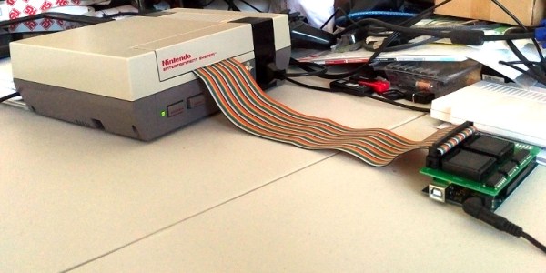
Most NES cartridges have two bits of memory, the PRG and CHR ROMs. [uXe] is breaking out the cartridge connector onto an exceptionally wide rainbow ribbon cable, and bringing it into a custom Arduino Mega shield loaded up with two 16K dual-port RAM chips. These RAM chips effectively replace the PRG and CHR ROMs Since these are dual-port RAM chips, they can be written to by the Arduino and read by the NES simultaneously.

The NES sees one port of the RAM and can read and write from it while the Arduino still has access to make changes to the other post while that’s happening. A trick like this opens up a whole world of possibilities, most obviously with tiling and other graphics tricks that can push beyond the console’s original capabilities. [uXe] is currently playing Arduboy games on the NES — a really neat trick to pull off. Well done [uXe]!

Be sure to check out the video below of the NES running some games from the Arduboy system. It seems to integrate seamlessly into the hardware, so if you’ve always had a burning desire to fix crappy graphics on some of your favorite games, or run some special piece of software on an NES, now might just be your time to shine.

Continue reading “The King Of All Game Genies In An Arduino”

Does This Demo Remind You Of Mario Kart? It Should!

Here’s a slick-looking VGA demo written in assembly by [Yianni Kostaris]; it’s VGA output from an otherwise stock ATmega2560 at 16MHz with no external chips involved. If you’re getting some Super Mario Kart vibes from how it looks, there’s a good reason for that. The demo implements a form of the Super Nintendo’s Mode 7 graphics, which allowed for a background to be efficiently texture-mapped, rotated, and scaled for a 3D effect. It was used in racing games (such as Super Mario Kart) but also in many others. A video of the demo is embedded below.

[Yianni] posted the original demo a year earlier, but just recently added detailed technical information on how it was all accomplished. The AVR outputs VGA signals directly, resulting in 100×120 resolution with 256 colors, zipping along at 60 fps. The AVR itself is not modified or overclocked in any way — it runs at an entirely normal 16MHz and spends 93% of its time handling interrupts. Despite sharing details for how this is done, [Yianni] hasn’t released any code, but told us this demo is an offshoot from another project that is still in progress. It’s worth staying tuned because it’s clear [Yianni] knows his stuff.

Continue reading “Does This Demo Remind You Of Mario Kart? It Should!”

Injecting SD Card Bootloaders

[Frank] has a Ultimaker2 and wanted to install a new bootloader for the microcontroller without having physical access to the circuitry. That means installing a new bootloader for the ATMega2560 without an In System Programmer, and as is usual on AVRs, the bootloader can only be edited with an ISP. Additionally, modifying the bootloader in any way runs the risk of corruption and a bricked circuit. That’s okay, because [Frank] knows how to do it, and he’s here to show you how.

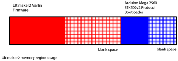
You can think of the memory layout of the ATMega in the Ultimaker as being split in half, with the printer firmware in the first half and the bootloader in the second half. There’s extra space in both halves, and that’s something that comes in very useful. When the circuit powers up, it jumps to the bootloader, does it’s thing, then jumps to the very beginning of the application code – a vector table – that starts up the actual firmware.

[Frank]’s trick to adding on to the bootloader is to place the SD card bootloader in the space normally reserved for applications, not where you would expect to find a bootloader. This code is accessed by the stock bootloader jumping into a modified vector table at the beginning of the application data that points to new executable code. That code is the actual SD card bootloader, but because it is in the application part of the memory, it can’t perform Flash writing or erasing. To fix that, a tiny bit of code is tacked onto the end of the bootloader for performing Flash writes and jumps back to the application part of memory.

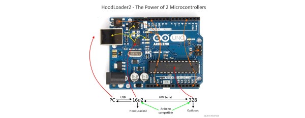
Using The Second Microcontroller On An Arduino

While newer Arduinos and Arduino compatibles (including the Hackaday.io Trinket Pro. Superliminal Advertising!) either have a chip capable of USB or rely on a V-USB implementation, the old fogies of the Arduino world, the Uno and Mega, actually have two chips. An ATMega16u2 takes care of the USB connection, while the standard ‘328 or ‘2560 takes care of all ~duino tasks. Wouldn’t it be great is you could also use the ’16u2 on the Uno or Mega for some additional functionality to your Arduino sketch? That’s now a reality. [Nico] has been working on the HoodLoader2 for a while now, and the current version give you the option of reprogramming the ’16u2 with custom sketches, and use seven I/O pins on this previously overlooked chip.

Unlike the previous HoodLoader, this version is a real bootloader for the ’16u2 that replaces the DFU bootloader with a CDC bootloader and USB serial function. This allows for new USB functions like HID keyboard, mouse, media keys, and a gamepad, the addition of extra sensors or LEDs, and anything else you can do with a normal ‘duino.

Setup is simple enough, only requiring a connection between the ‘328 ISP header and the pins on the ’16u2 header. There are already a few samples of what this new firmware for the ’16u2 can do over on [Nico]’s blog, but we’ll expect the number of example projects using this new bootloader to explode over the coming months. If you’re ever in an Arduino Demoscene contest with an Arduino and you’re looking for more pins and code space, now you know where to look.

Roboceratops: A Robot Dinosaur That Defies Extinction

roboceratopsInspired by a childhood love of dinosaurs, [Robert] set out to build a robotic dinosaur from the Ceratopsian family. After about a year of design, building, and coding, he has sent us a video of Roboceratops moving around gracefully, chomping a rope, and smoothly wagging his tail.

Roboceratops is made from laser-cut MDF and aluminium bars in the legs. That’s not cookie dough on those legs, it’s upholstery foam, and we love the way [Robert] has shaped it. Roboceratops has servos in his jaw, neck, tail, and legs for a total of 14-DOF. You can see the servo specifics and more in the video description. [Robert] has full kinematic control of him through a custom controller and is working to achieve total quadrupedal locomotion.

Inside that custom controller is an Arduino Mega 2560, an LCD, and two 3-axis analog joysticks that control translation, height, yaw, pitch, and jaw articulation. For now, Roboceratops receives power and serial control through a tether, but [Robert] plans to add an on-board µC for autonomous movement as well as wireless, a battery, an IMU, and perhaps some pressure/contact detection in his feet.

The cherry on top of this build is the matching, latching custom carry case that has drawers to hold the controller, power supply, cable, tools, and spare parts. Check out Roboceratops after the break.

Continue reading “Roboceratops: A Robot Dinosaur That Defies Extinction”