CP/M 6502-Style

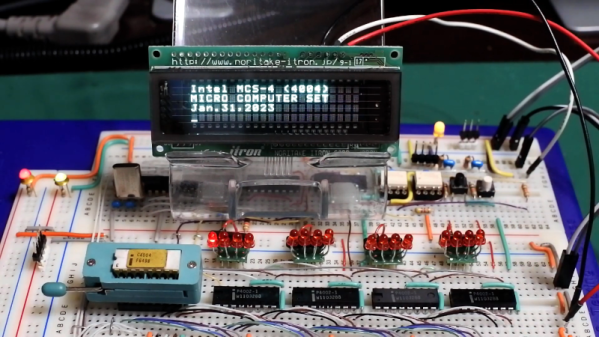
There are projects you create to share with the world, but there are also those you do just because you want something for yourself. Lucky for us, [Dietrich-L]’s 30-year-long project to create CPM-65, a CP/M-like OS for the 6502, has become both.

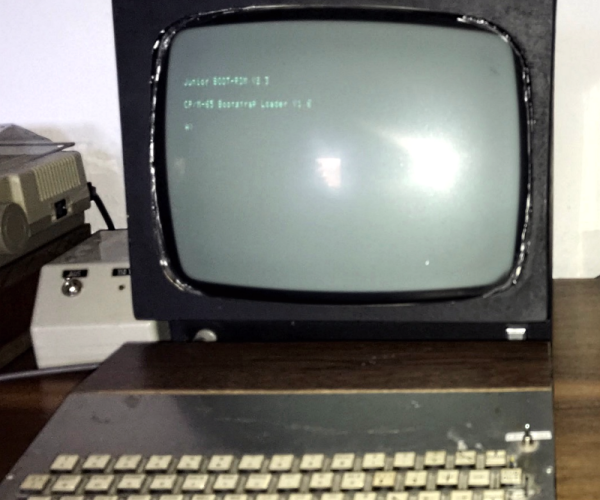
[Dietrich-L] does admit that the documentation is “sparse” and “for my personal needs.” Still, the OS has most of what you’d expect and runs well on the target system, a heavily-modified Elektor Junior with 57 kB of RAM. The disk structure is compatible with CP/M, although the Transient Program Area (TPA) apparently starts at $200, which is a bit different from a typical CP/M. Apparently, the system uses some low memory which necessitated the relocation. Just in case you were hoping, CPM-65 doesn’t emulate an 8080 system, so you can’t run normal CP/M programs. You just get a similar operating environment and tools.

The 31 commands listed include an assembler, BASIC, Forth, an editor, and some disk tools, along with a debugger. Xmodem is available, too. Everything is written in assembly for the CPM-65 assembler, so bootstrapping could be an issue if you need to make any changes.

Speaking of changes, there is some documentation in the docs sub-directory, including the layout of [Dietrich-L]’s system, which would be handy if you were trying to run this on your own hardware. You’ll also find basic commands for the editor, details of the assembler, and some other documents.

[Dietrich-L] notes that he was unaware when he started the project that there were other similar projects. DOS/65 (which has a port for the Commodore 64), OUP/M (which hasn’t been updated since 1983), and CPM65 (apparently no relation, but very impressive), which appeared in 2022.

If you need a 6502 computer, grab a breadboard, although adding the disk drive is an exercise left to the reader. Or, grab an FPGA but expect more work.

Thanks [Stephen Walters] for the tip!

Machine Learning Helps Electron Microscopy

Machine learning is supposed to help us do everything these days, so why not electron microscopy? A team from Ireland has done just that and published their results using machine learning to enhance STEM — scanning transmission electron microscopy. The result is important because it targets a very particular use case — low dose STEM.

The problem is that to get high resolutions, you typically need to use high electron doses. However, bombarding a delicate, often biological, subject with high-energy electrons may change what you are looking at and damage the sample. But using reduced electron dosages results in a poor image due to Poisson noise. The new technique learns how to compensate for the noise and produce a better-quality image even at low dosages.

Continue reading “Machine Learning Helps Electron Microscopy”

Linux Fu: Gum Up Your Script

We often write quick bash scripts and judging by the comments, half of us use bash or a similar shell to pop out quick, useful scripts, and half of us think that’s an abomination, and you should only use bash for your command line and resort to something more like a traditional language to do anything else. If you’re in the former camp, you’re probably cursing your allegiance when you need to make your bash scripts more interactive.

Gum can help. It’s a utility that can handle your script input and output with a little flair while requiring almost no effort on your part.

The command looks simple, but it has twelve subcommands, each with myriad options. But you can break down the functions into a few simple categories. The input commands let you prompt for a line of input or a bunch of lines of input. You can also create a pick list or a yes/no type of prompt. There’s also a file picker and a filter, sort of like fzf.

Continue reading “Linux Fu: Gum Up Your Script”

EPROM Does VGA

If you wanted to create a VGA card, you might think about using an FPGA. But there are simpler ways to generate patterns, including an old-fashioned EPROM, as [DrMattRegan] points out in a recent video.

Generating video signals is an exercise in periodicity. After all, an old-fashioned CRT just scans at a certain horizontal frequency and refreshes the entire screen each time it starts over. VGA is made to drive this technology. An EPROM chip can easily generate repeating patterns when driven by a counter at a known frequency.

As you might expect, there were a few software glitches to work out, but in the end, the circuit did its job, displaying a fixed image on a VGA monitor.

If you haven’t run into [Matt] before, he has a complete series on how he built a “wire-by-wire” Apple II clone. We will warn you, though. Don’t click on the link unless you have some spare time. The 18 videos take over two hours to work through, but there is some beautiful prototyping and a lot of good information in them.

You can go even lower tech for a VGA card, if you like. Just try not to look like this breadboard.

Continue reading “EPROM Does VGA”

A Comprehensive Look At FDM Supports

When we first started 3D printing, we used ABS and early slicers. Using supports was undesirable because the support structures were not good, and ABS sticks to itself like crazy. Thankfully today’s slicers are much better, and often we can use supports that easily detach. [Teaching Tech] shows how modern slicers create supports and how to make it even better than using the default settings.

The video covers many popular slicers and their derivatives. If you’ve done a lot with supports, you might not find too much of this information surprising, but if you haven’t printed with supports lately or tried things like tree supports, you might find a few things that will up your 3D printing game.

One thing we really like is that the video does show different slicers, so regardless of what slicer you like to use, you’ll probably find exactly what different settings are called. Of course, because slicers let you examine what they produce layer-by-layer, you can do like the video and examine the results without printing. [Michael] does do some prints with various parameters, though, and you can see how hard or easy the support removal is depending on some settings. The other option is to add support to your designs, as needed manually, or — even better — don’t design things that need support.

This video reminded us of a recent technique we covered that added a custom support tack to help the slicer’s automatic support work better. If you want a longer read on supports that also covers dissolvable support, we’ve seen that, too.

Continue reading “A Comprehensive Look At FDM Supports”

The 4004 Upgrade You’ve Been Waiting For

You know how it is. You have an older computer, and you can’t run the latest software on it. Time to upgrade, right? Well, if you have been in this situation a very long time, [ryomuk] may have an answer for you. The emu8080on4004 project (Google Translate) offers a way to run 8080 code on a 4004 CPU. Finally!

The 4004 development board is a homebrew affair, and the emulator works well enough that an 8080 Tiny BASIC interpreter ran with very few changes to the source code. You can see it working in the video below. It would be cool to run CP/M, but we imagine that would be a little harder, especially resource-wise.

A few things are missing. For example, the DAA instruction doesn’t exist, and there are no provisions for interrupts. There’s only one I/O port, and using the IN instruction will block until you receive a serial port character. There is an option to implement the parity flag in the 8080 flags register, but its operation is untested.

Still, pretty impressive for a 4-bit CPU running at 740 kHz with very little memory. If you want to see more about the development board itself, check out the second video below. Want to know more about the chip that launched a family of processors that is still around? Read its biography. You can also read about the designer who put his signature on the die.

Continue reading “The 4004 Upgrade You’ve Been Waiting For”

IBIS Models Explained

If you’ve worked with circuit simulation, you may have run into IBIS models. The acronym is input/output buffer information, and while you can do a lot without having to deal with IBIS, knowing about it can help you have a successful simulation.

IBIS is an industry-standard format that uses ASCII text to describe voltage versus current and voltage versus time about some device’s digital input and output pins. This allows precise simulation without revealing the device’s internals, which is important to some vendors. The first post of this two-part series talks about what IBIS is and how it got started. The second part explains creating and using LTSpice to create your own IBIS models. It also covers why you might want to do that.

Of course, if you don’t care about revealing the internals of a device, you could just create a Spice simulation. However, many tools will accept both models, so it is useful to know how to produce either kind of model. In fact, to create an IBIS model, you’ll want to use a Spice model to generate the data for the IBIS model, so it is a good bet you’ll have both, even if you choose to only publish the IBIS models.

If you need a refresher on Spice, we have a series. If you prefer using something different, try Micro-Cap 12, which was commercial, but went free a few years ago.