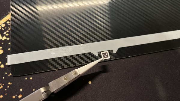
The Bambu X1C 3D printer is a machine known for its speed, and it has a number of useful features like automatic build platform recognition. Factory build platforms are marked with an identifier code, and thanks to [elumspe] it’s now possible to make your own identifiers to stick onto third-party platforms and have the printer recognize them as though they were factory offerings. There’s even a super handy 3D-printable alignment tool that ensures the identifier goes in the correct spot, which is a nice touch.
The identifier codes aren’t DRM so much as they are a way for the printer to verify that the installed build platform matches the slicer settings before a print begins, and throw up a warning if it doesn’t. The printer is perfectly happy to use third-party build surfaces, but since they lack an identifier, the printer will throw a warning each time. One solution is to simply disable checking the build platform before a print, but for those who would prefer to have the printer see what it expects to see, printing a small 2D barcode to stick on is an easy way to do it.
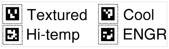
We see these sometimes called QR codes, but they look more like AprilTags. Both are types of 2D barcode, but while QR codes can encode a variety of information types, AprilTags are simpler and usually represent identifiers. In this case, they’re an appropriate way to let a camera-enabled printer know what kind of build plate is installed.
AprilTags are common in computer vision applications, and even relatively modest hardware can detect and decode them almost in real time. AprilTags are convenient and easy to use, as this gate access system demonstrates.