FreeCAD Version 1.0 Released

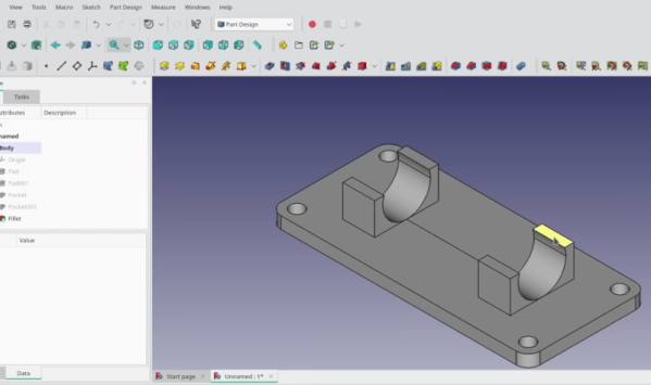
After 22 years of development, FreeCAD has at long last reached the milestone of version 1.0. On this momentous occasion, it’s good to remember what a version 1.0 is supposed to mean, as also highlighted in the release blog post: FreeCAD is now considered stable and ready for ‘real work’. One of the most important changes here is that the topological naming problem (TNP) that has plagued FreeCAD since its inception has now finally been addressed using Realthunders’ mitigation algorithm, which puts it closer to parity here with other CAD packages. The other major change is that assemblies are now supported with the assembly workbench, which uses the Ondsel solver.

Other changes include an updated user interface and other features that should make using FreeCAD easier and closer in line with industry standards. In the run-up to the 1.0 release we already addressed the nightmare that is chamfering in FreeCAD, and the many overlapping-yet-uniquely-incomplete workbenches, much of which should be far less of a confabulated nightmare in this bright new 1.0 future.

Naturally, the big zero behind the major version number also means that there will still be plenty of issues to fix and bugs to hunt down, but it’s a promising point of progress in the development of this OSS CAD package.

The End Of Ondsel And Reflecting On The Commercial Prospects For FreeCAD

Within the world of CAD there are the well-known and more niche big commercial players and there are projects like FreeCAD that seek to bring a OSS solution to the CAD world. As with other OSS projects like the GIMP, these OSS takes on commercial software do not always follow established user interactions (UX), which is where Ondsel sought to bridge the gap by giving commercial CAD users a more accessible FreeCAD experience. This effort is now however at an end, with a blog post by Ondsel core team member [Brad Collette] providing the details.

The idea of commercializing OSS is by no means novel, as this is what Red Hat and many others have done for decades now. In our article on FOSS development bounties we touched upon the different funding models for FOSS projects, with the Linux kernel enjoying strong commercial support. The trick is of course to attract such commercial support and associated funding, which is where the development on the UI/UX and feature set of the core FreeCAD code base was key. Unfortunately the business case was not strong enough to attract such commercial partners and Ondsel has been shutdown.

As also discussed on the FreeCAD forum, the Ondsel codebase will likely be at least partially merged into the FreeCAD code, ending for now the prospect of FreeCAD playing in the big leagues with the likes of AutoCAD.

Thanks to [Brian Harrington] for the tip.

FreeCAD Is Near 1.0

The open-source parametric 3D modelling software, FreeCAD, is out in a release candidate for version 1.0.  If you’ve tried FreeCAD before and found a few showstoppers, it might be a good time for you to test it out again because the two biggest of them have been solved in this latest version.

First, version 1.0 finally implements a solution to the “topological naming problem”. Imagine you want to put a hole into a surface. The program needs to know on which surface to put the hole, and so it refers to this surface by name / number. Now imagine you subdivide the surface, and both subsections get new names. Where does your hole go now?  If you want to dig into the issue, the inimitable [MangoJelly] has a great video about the topo naming problem. Practically, there were workarounds, like only adding chamfers after the main design has stabilized, but frankly it was a hassle to remember all of the tricks. This is a huge fix.

The second big fix concerns assemblies.  Older versions of FreeCAD were great for making single parts, but combining them all together inside the CAD program was always janky.  Version 1.0 combines the previous two patchwork assembly workbenches into one, and it’s altogether more pleasant to use. The constraints of how two parts move when held together with an axle just works now, and this is a big deal for multi-part models.

If you’re coming from any other parametric CAD program, most of FreeCAD will seem familiar to you, but there will also be workflow differences that will take some getting used to. In trade, what do you get? Scriptability in Python, real open source software, and all of the bells and whistles for free. Now that its two biggest pain points have been addressed,  FreeCAD has become a lot easier to love. We’re looking forward to some good V1.0 tutorials in the future, and we’ll keep you posted when we find them.

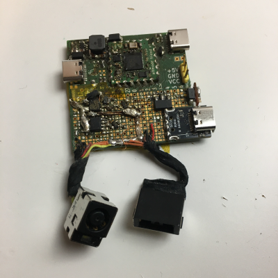
A FreeCAD sticker, a FreeCAD pencil, a Hackaday Jolly Wrencher SAO PCB and the board-to-be-encased next to each other

FreeCAD Foray: Shells For All Our PCBs

Are you the kind of hacker who tries to pick up FreeCAD, but doesn’t want to go through a tutorial and instead pokes around the interface, trying to transfer the skills from a CAD suite you’ve been using before? I’ve been there too, and in my experience, FreeCAD doesn’t treat such forays lightly. It’s a huge package that enables everything from architecture to robotics design, so if you just want a 3D-printed case for a PCB project, the hill can be steep. So let’s take that first simple project as an example, and see if it helps you learn a little bit of FreeCAD.

This board needs a case – badly.

As motivation, I recently built a USB-C PSU board that uses a DC PSU and does the USB-C handshaking to provide 20 V to a laptop. It is currently my only 100 W USB-C PSU, and my 60 W PSU just died, which is why I now use this board 24/7. I have brought it on two different conferences so far, which has highlighted a problem – it’s a board with tons of exposed contacts, which means that it isn’t perfectly travel-friendly, and neither it is airport-friendly – not that I won’t try and bring it anyway. So, currently, I have to watch that nothing shorts out – given the board has 3.3 V close to 20 V at 9 A, it’s a bit of a worry.

This means I have to design some sort of case for it. I was taught SolidWorks in the half a year that I spent in a university, and honestly, I’m tired of the licensing and proprietary format stuff. When it comes to more hobbyist-accepted tools like Fusion360, I just don’t feel like exchanging one proprietary software for another. So, FreeCAD is the obvious choice – apart from OpenSCAD, which I know and love, but I don’t always want to think up fifteen variable names for every silly little feature. That, and I also want to fillet corners every now and then.

For a full-open-source workflow, today’s PCB is designed with KiCad, too. Let’s see about installing FreeCAD, and the few things you need to import a KiCad board file into FreeCAD.

Continue reading “FreeCAD Foray: Shells For All Our PCBs”

Come For The PCB Holder, Stay For The Tour Of FreeCAD

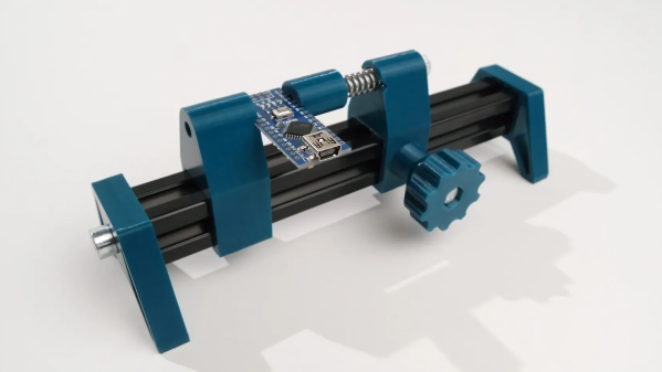
PCB holders are great tools. Not only is the PCB Solder Fren from [PistonPin] a nice DIY design, it offers some insight into the parts design process with FreeCAD.

This design nicely demonstrates FreeCAD’s workflow for designing parts.

The PCB holder uses 3D-printed parts, M5 hardware, a length of 2020 aluminum extrusion, and one spring to create a handy and adjustable design that accommodates a variety of PCB sizes and shapes. If the ends of the extrusion are threaded, the end caps can be screwed in. Otherwise, a little glue ought to do the trick.

Want a little more insight into what making a part like this involves? [Jo Hinchliffe] at FreeCAD reached out to [PistonPin] for more detail and has a blog post explaining the workflow and steps involved in this part. As a bonus, STEP files and the FreeCAD project file are all included!

Not only is FreeCAD simple to use, but it’s also flexible enough to accommodate custom, niche extensions like a Rocketry workbench, so be sure to give it a look for your open-source CAD needs.

Throw FreeCAD Some Curves

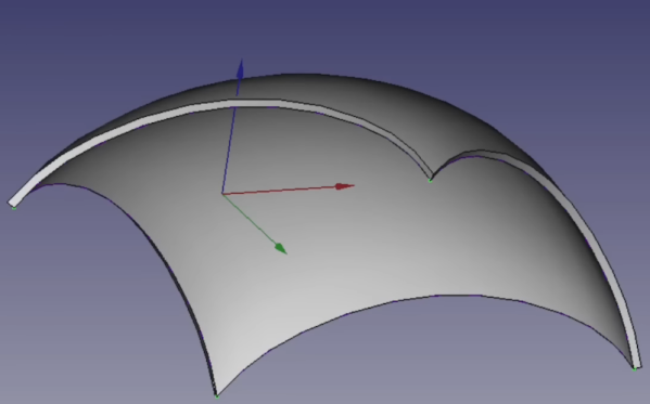
[Mango Jelly] got a question from someone trying to model a phone box with a complex curved roof. We have to admit that when we saw it, we knew it would be hard to model well. Naturally, there are several ways it could be one, but [Mango Jelly] used the curves workbench in FreeCAD to produce a wireframe of the shape, and you can see how that works in the video below.

The curve bench didn’t sound familiar to us, and that’s because it is an add-on workbench. He starts with a sketch of a curve, constrained to be symmetrical. Then the draft workbench allowed a rotation to convert the curve into a nice skeleton of the curved roof.

The curves workbench can create a Gordon surface over that skeleton. You can extrude that into a solid object. There are still some details to add, though, and you’ll see how each part of the roof takes shape.

Watching videos like this reminds us that we use a small fraction of what FreeCAD can do. You’ll probably pick up at least one tip from this video. If you need a quick basic tutorial, try the one from [NovaSpirit]. Or, try a longer one.

Continue reading “Throw FreeCAD Some Curves”

FreeCAD Is Simple, According To This Tutorial

Remember learning to tie your shoes or ride a bike? Like many things, that’s easy once you know how to do it, but seems impossible before you learn. [NovaSpirit] asserts that Freecad is simple, and provides a simple walkthrough to create a part in the video below.

If this were riding a bike, this tutorial would be akin to watching someone ride a bike to pick up tips. You’d probably still want to have someone explain details to you before you attempt it yourself.

Continue reading “FreeCAD Is Simple, According To This Tutorial”