FreeCAD Takes Off With A Rocket Design Workbench

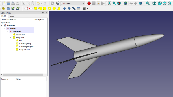
Here’s how FreeCAD works: the program’s design space is separated into different “workbenches”, each of which is intended for a particular set of operations, and a piece of work can be moved between them as needed. There is a sketching workbench, a part design workbench, and now a Rocket workbench has been added to the healthy ecosystem of FreeCAD add-ons. There’s even a series of video tutorials; ain’t open source grand?

It all started when [concretedog] posted on the FreeCAD forums, making a strong case for a Rocket-themed workbench. People got interested, and a short while later [DavesRocketShop] had some useful tools up and running. Here’s a blog post by [concretedog] which goes into detail and background, and while the Rocket workbench is available via FreeCAD’s add-on manager, the very latest experimental builds are available for manual installation on [Dave]’s GitHub repository.

This sort of development and utility is exactly the kind of thing our own Elliot Williams was describing when he made the point that one of open source’s greatest strengths is in the little things, like the FreeCAD ecosystem letting people scratch strange and specific itches, and the ability to share those solutions with others.

FreeCAD Debugging

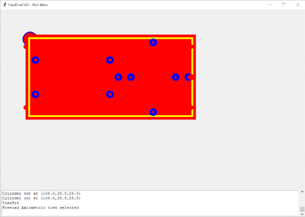
Powerful software programs often have macro programming languages that you can use, and if you know how to program, you probably appreciate them. However, sometimes the program’s built-in debugging facilities are lacking or even nonexistent If it were just the language, that wouldn’t be such a problem, but you can’t just grab a, for example, VBA macro from Microsoft Word and run it in a normal Basic interpreter. Your program will depend on all sorts of facilities provided by Word and its supporting libraries. [CrazyRobMiles] was frustrated with trying to debug Python running inside FreeCAD, so he decided to do something about it.

[Rob’s] simple library, FakeFreeCad, gives enough support that you can run a FreeCAD script in your normal Python development environment. It only provides a rude view of what you are drawing, but it lets you explore the flow of the macro, examine variables, and more.

Continue reading “FreeCAD Debugging”

FreeCAD Parametrics Made Simple

Simple drafting programs just let you draw like you’d use a pencil. But modern programs use parametric models to provide several benefits. One is that you can use parameters to change parts of your design and other parts will alter to take account of your changes. The other advantage is you can use one model for many similar but different designs. [Brodie Fairhall] has a nice video about how to use parameters in FreeCAD.

The nice thing about parameters is they don’t have to be just constants. You can put in formulae as well. For example, you could define one line as being twice as big as another line. You provide various constraints and parameters and FreeCAD works out the shape for you, keeping all the constraints and formulae satisfied.

Continue reading “FreeCAD Parametrics Made Simple”

FreeCAD Vs SolveSpace

When you are ready to design real things, you’ll find simple CAD programs can be pretty limiting. Serious modern designs tend to use parametric modeling where you don’t necessarily set dimensions and positions of everything but instead constrain the design by describing the relationship between different elements. For example, you can create a vertical line and constrain other lines to be parallel, perpendicular, or form a given angle with that line. There are many tools that can do that, including FreeCAD and SolveSpace, two programs that [Joko Engineeringhelp] uses to create a complex compressor blade and it really shows the differences and similarities between the two tools.

You probably don’t need this particular design, but watching over someone’s shoulder while they do a complex design can be very valuable. Being able to see the differences between the two tools might convince you to learn one or the other or maybe even switch.

Continue reading “FreeCAD Vs SolveSpace”

FreeCAD TechDraw Workbench Tutorial

FreeCAD started out a little shaky, but it has gotten better and better. If you are trying to draw a schematic, it probably isn’t the best way to do it. However, it is a great graphical alternative to OpenSCAD for 3D printing and even incorporates OpenSCAD if you don’t want to choose. However, if you have a 3D part — regardless of how you want to create it in real life — having a proper mechanical drawing is very valuable. FreeCAD’s TechDraw workbench makes this very easy and [Joko] has a tutorial that shows exactly how to do it.

Machinists everywhere are used to looking at these drawings that typically show a top view, a front view, and a side view. The program will automatically project the views you select and then allows you to pick dimensions. It creates them and keeps them up to date if you change them in the model later.

Continue reading “FreeCAD TechDraw Workbench Tutorial”

KiCad And FreeCAD Hack Chat

Join us Wednesday at noon Pacific time for the KiCad and FreeCAD Hack Chat led by Anool Mahidharia!

The inaugural KiCon conference is kicking off this Friday in Chicago, and KiCad aficionados from all over the world are gathering to discuss anything and everything about the cross-platform, open-source electronic design automation platform. As you’d expect, Hackaday will have a presence at the conference, including a meet and greet after party. There’ll also be talks by a couple of our writers, including Anool Mahidharia, who’ll be taking time out of his trip to the States to drop by the Hack Chat with a preview of his talk, entitled “Fast 3D Model Creation with FreeCAD”.

Join us for the KiCad and FreeCAD Hack Chat this week with your questions about KiCad and FreeCAD. If you’ve got some expertise with electronic design tools, make sure you come by and contribute to the discussion too — we’d love to hear your insights. And as always, you can get your questions queued up by leaving a comment on the KiCad and FreeCAD Hack Chat event page and we’ll put them on the list for the Hack Chat discussion.

join-hack-chatOur Hack Chats are live community events in the Hackaday.io Hack Chat group messaging. This week we’ll be sitting down on Wednesday, April 24, at noon, Pacific time. If time zones have got you down, we have a handy time zone converter.

Click that speech bubble to the right, and you’ll be taken directly to the Hack Chat group on Hackaday.io. You don’t have to wait until Wednesday; join whenever you want and you can see what the community is talking about.

Add Slots And Tabs To Your Boxes In FreeCAD

FreeCAD is a fairly sophisticated, open-source, parametric 3D modeler. The open-source part means that you can bend it to your will. [Alexandre] is working on a module that lets him easily add tabs, finger joints, and t-slots to models (YouTube link, embedded down under).

Right now the plugin is still experimental, but it looks usable. In the video demo, [Alexandre] builds up a simple box, and then adds all manner of physical connective pieces to it. You’ll note that the tabs look like they’re pieces added on to the main face — that’s because they are! He then exports the outlines to SVG and erases the lines that separate the tabs from the sides, and hands these files off to his laser cutter. Voilà! A perfect tab-and-t-slot box, with only a little bit of hand-work. ([Alexandre] mentions that it’s all still very experimental and that you should check out your design before sending it to the laser.)

Continue reading “Add Slots And Tabs To Your Boxes In FreeCAD”