Hackaday Dictionary: Software Defined Radio (SDR)

We are entering a new era of radio technology. A new approach to building radios has made devices like multi-band cell phones and the ubiquitous USB TV receivers that seamlessly flit from frequency to frequency possible. That technology is Software Defined Radio, or SDR.

A idealized radio involves a series of stages. Firstly, an antenna receives the radio signal, converting it into an electrical signal. This signal is fed into a tuned resonator which is tuned to a particular frequency. This amplifies the desired signal, which is then sent to a demodulator, a device which extracts the required information from the carrier signal. In a simple radio, this would be the audio signal that was encoded by the transmitter. Finally, this signal is output, usually to a speaker or headphones.

A replica foxhole crystal set. Photo: Bill Jackson

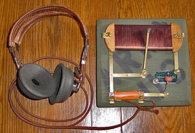
That’s how your basic crystal radio works: more sophisticated radios will add features like filters that remove unwanted frequencies or additional stages that will process the signal to create the output that you want. In an FM radio, for example, you would have a stage after the demodulator that detects if the signal is a stereo one, and separates the two stereo signals if so.

To change the frequency that this radio receives, you have to change the frequency that the resonator is tuned to. That could mean moving a wire on a crystal, or turning a knob that controls a variable capacitor, but there has to be a physical change in the circuit. The same is true of the additional mixing stages that refine the signal. These circuits may be embedded deeply in the guts of the radio, but they are still there. This is the limitation with normal receivers: the radio can’t receive a signal that is outside the range that the resonator circuit can tune to, or change the way it is demodulated and processed. If you want to receive multiple frequency bands or different types of signals, you need to have separate pathways for each band or type of signal, physically switching the signal between them. That’s why you have physical AM/FM switches on radios: they switch the signal from an AM radio processing path to an FM one.

Software Defined Radios remove that requirement. In these, the resonator and demodulator parts of the radio are replaced by computerized circuits, such as analog to digital converters (ADCs) and algorithms that extract the signal from the stream of data that the ADCs capture. They can change frequencies by simply changing the algorithm to look for another frequency: there is no need for a physical change in the circuit itself. So, an SDR radio can be tuned to any frequency that the ADC is capable of sampling: it is not restricted by the range that a resonator can tune to. Similarly, the demodulator that extracts the final signal you want can be updated by changing the algorithm, changing the way the signal is processed before it is output.

This idea was first developed in the 1970s, but it didn’t really become practical until the 1990s, when the development of flexible field-programmable gate array (FPGA) chips meant that there was enough processing power available to create single chip SDR devices. Once programmed, an FPGA has no problem handing the complex tasks of sampling, demodulating and processing in a single device.

Most modern SDRs don’t just use a single chip, though. Rather than directly converting the signal to digital, they use an analog front end that receives the raw signal, filters it and converts it down to a fixed frequency (called the intermediate frequency, or IF) that the ADCs in the FPGA can more easily digitize. This makes it cheaper to build: by converting the frequency of the signal to this intermediate frequency, you can use a simpler FPGA and a cheaper ADC, because they don’t have to directly convert the maximum frequency you want to receive, only the IF. As long as the front end can convert a band of signals down to an intermediate frequency that the FPGA can digitize, the SDR can work with it.

bladerf
The BladeRF, a modern SDR device that can receive and transmit signals between 300 MHz and 3 GHz

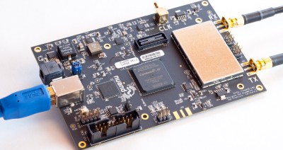
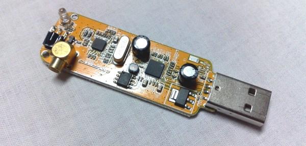
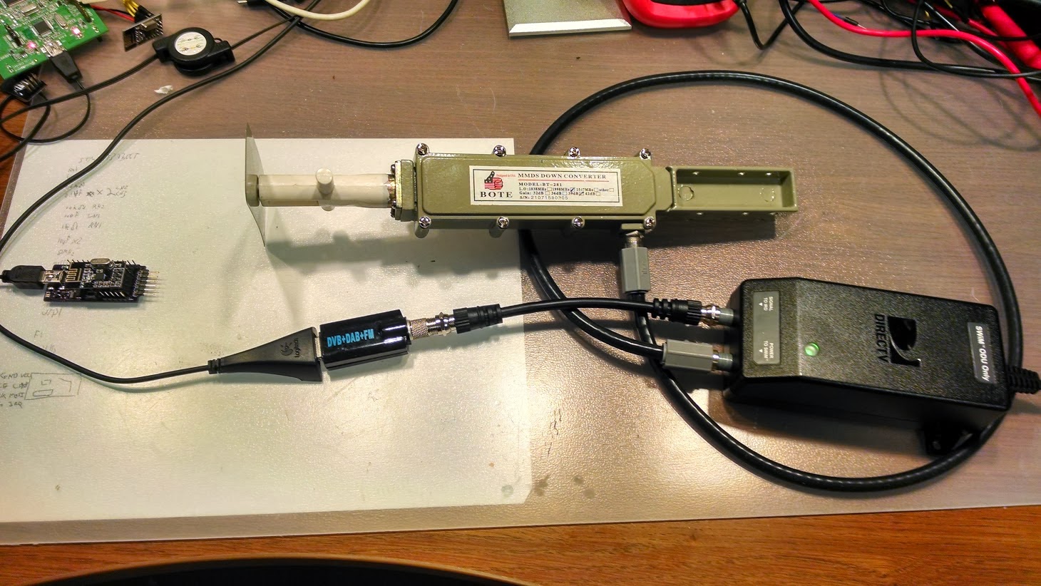
This flexibility means that SDR devices can handle a huge range of signals at relatively low cost. The $420 BladeRF, for instance, can receive and transmit signals from 300 MHz to 3.8 GHz at the same time, while the $300 HackRF One can work with signals from 1 MHz up to an incredible 6 GHz. The ability of the BladeRF to both receive and transmit means that you can use it to build your own GSM phone network, while the low cost of the HackRF One makes it a favorite of radio hackers who want to do things like make portable radio analyzers. Mass produced models are even cheaper: by hacking a $20 USB TV receiver that contains an SDR, you can get a radio that can, with a suitable antenna, do things like track airplanes or receive satellite weather images. And all of this is possible because of the idea of Software Defined Radio.

[Main image source: DVB dongle by Dsimic on Wikipeda CC-BY-SA]

Verifying A Wireless Protocol With RTLSDR

rtlsdr_nrf905_rtlizer

[Texane] is developing a system to monitor his garage door from his apartment. Being seven floors apart, running wires between the door and apartment wasn’t an option, so he turned to a wireless solution. Testing this wireless hardware in an apartment is no problem, but testing it in situ is a little more difficult. For that, he turned to software defined radio with an RTLSDR dongle.

The hardware for this project is based around a TI Stellaris board and a PTR8000 radio module. All the code for this project was written from scratch (Github here), making it questionable if the code worked on the first try. To test his code, [Texane] picked up one of those USB TV tuner dongles based around the RTL2832U chipset. This allowed him to monitor the frequencies around 433MHz for the packets his hardware should be sending.

After that, the only thing left to do was to write a frame decoder for his radio module. Luckily, the datasheet for the module made this task easy.

[Texane] has a frame decoder for the NRF905 radio module available in his Git. It’s not quite ready for serious applications, but for testing a simple radio link it’s more than enough.

Sniffing And Decoding Bluetooth LE Advertising Packets And NRF24L01+ Comms. For Under $30

[Omri] just documented his journey to sniff and decode the protocol used by the popular NRF24L01+ transceiver off the air for very cheap. As he was designing a mesh network code and needed a way to monitor/debug the overall network performance, [Omri] decided to look for some RF hardware.

We’re sure that most of our readers are familiar with Software Defined Radio (SDR), which not so long ago became popular when some engineer discovered hidden registers inside Realtek RTL2832U chip, allowing many DVB-T dongles to be converted into RF listening devices. Unfortunately for [Omri], most of them have a maximum listening frequency of 2.2GHz, while the NRF24L01+ emits at 2.4GHz. The solution? Buy a 2.2-2.4GHz antenna from Aliexpress with a low-noise block downconverter (LNB), used for a Multichannel Multipoint Distribution Service (MMDS). The LNB therefore takes the 2.2-2.4GHz signal and downconverts it to around 400MHz, allowing any RTL-SDR-compatible DVB-T dongle to listen to the NRF communications. A program was then written to decode the RF signal and output the sniffed data in realtime.

Pager Message Sniffing With RPi And SDR

rpi-pager-message-sniffing

The 1990’s called, they want you to use modern technology to listen in on your friends’ pager messages. Seriously, how many people are still using pagers these days? We guess you can find out by building your own Software-Define Radio pager message decoder.

[Sonny_Jim] bought an RTL2832 based USB dongle to listen in on ADS-B airplane communications only to find out the hardware wasn’t capable of communicating in that bandwidth range. So he set out to find a project the hardware was suited for and ended up exploring the POCSAG protocol used by paging devices. It turns out it’s not just used for person-to-person communications. There are still many automated systems that use the technology.

Setting things up is not all that hard. Reading the comments on the project log show some folks are having dependency issues, but these sound rather banal and will be a good chance for you to brush up on your Linux-fu. Once all the packages are installed you’re simply working with text which can be displayed in a myriad of ways. [Sonny] set up a text files on the Pi’s webserver so that he can check out the latest captures from a smartphone.

[Image Source]

Still More Software Defined Radio Fun On The Mac

Even though the world of software defined radio started out as a Linux-only endeavor, several recent software releases have put the ball fully into the court of OS X users. [hpux735]’s new Cocoa Radio release provides a (nearly) fully functional software defined radio for anyone with a USB TV tuner and a mac.

Earlier this week, we saw (and tested)  [Elias]‘ port of gqrx and were reasonably impressed. [hpux735]’s app does the same job and also provides the source so you can compile it yourself.

Previously, [hpux735] ported the osmocom driver for these RTL2832U-based USB TV tuner dongles to the Mac and wrote a small Cocoa driver. The new Cocoa Radio software uses this driver and adds all the features you’d expect from a software radio package; in the title pic for this post, you can see a top 40 radio station near my house and their insipid hatred of dynamic range.

[hpux735] posted a few videos of his development process. You can check those out after the break.

Continue reading “Still More Software Defined Radio Fun On The Mac”

Hackaday Links: September 7, 2012

MakerSlide, European edition

We’re all familiar with the MakerSlide, right? The linear bearing system that has been turned into everything from motorized camera mounts to 3D printers is apparently very hard to source in Europe. A few folks from the ShapeOko forum have teamed up to produce the MakerSlide in the UK. They’re running a crowdsourced project on Ulule, and the prices for the rewards seem very reasonable; €65/£73 for enough extrusion, v-wheels, and spacers to make an awesome CNC router.

Kerf bending and math

A few days ago, I made an offhand remark asking for an engineering analysis of kerf bending. [Patrick Fenner] of the Liverpool hackerspace DoES already had a blog post covering this, and goes over the theory, equations, and practical examples of bending acrylic with a laser cutter. Thanks for finding this [Adrian].

276 hours well spent

[Dave Langkamp] got his hands on a Makerbot Replicator, one thing led to another, and now he has a 1/6 scale model electric car made nearly entirely out of 3D printed parts. No, the batteries don’t hold a charge, and the motor doesn’t have any metal in it, but we’ve got to admire the dedication that went in to this project.

It was thiiiiiiis big

If you’ve ever tried to demonstrate the size of an object with a photograph, you’ve probably placed a coin of other standard object in the frame. Here’s something a little more useful created by [Phil]. His International Object Sizing Tool is the size of a credit card, has inch and cm markings, as well as pictures of a US quarter, a British pound coin, and a one Euro coin. If you want to print one-off for yourself, here’s the PDF.

Want some documentation on your TV tuner SDR?

The full documentation for the E4000/RTL2832U chipset found in those USB TV tuner dongles is up on reddit. Even though these chips are now out of production (if you haven’t bought a proper tuner dongle yet, you might want to…), maybe a someone looking to replicate this really cool device will find it useful.

Real Time GPS Decoding With Software Defined Radio

In case the Realtek RTL2832u-based USB TV tuner dongle isn’t useful enough, the folks behind a project to get a software defined GPS receiver off the ground successfully plotted GPS data in real-time with this very inexpensive radio.

Previously, we’ve seen these dongles grab data from GPS satellites – useful if you’re building a GPS-based clock – but this build required hours of data collection to plot your location on a map.

The folks working on the GNSS-SDR project used an RTL2832 USB TV tuner and a Garmin active GPS antenna to track up to four GPS satellites in real-time and plot a location accurate to about 200 meters.

The Google Earth plot for this post shows the data collected by the GNSS-SDR team; the antenna was fixed at the red arrow for the entirety of the test, and the  yellow lines represent a change in the calculated location every 10 seconds. Amazing work, and only goes to show what this remarkable piece of hardware is capable of.