Rapid Prototyping PCBs With The Circuit Graver

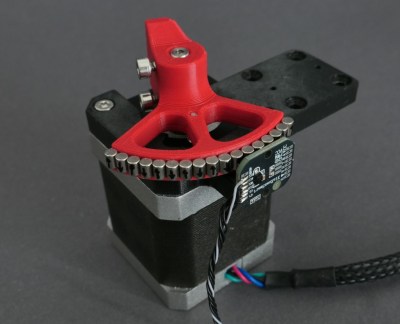
Walking around the alley at Hackaday Supercon 2024, we noticed an interesting project was getting quite a bit of attention, so we got nearer for a close-up. The ‘Circuit Graver’ by [Zach Fredin] is an unconventional PCB milling machine, utilizing many 3D printed parts, the familiar bed-slinger style Cartesian bot layout and a unique cutting head. The cutting tool, which started life as a tungsten carbide lathe tool, is held on a rotary (‘R’) axis but can also move vertically via a flexure-loaded carriage driven by a 13 kg servo motor.

The stocky flexure took a lot of iteration, as the build logs will show. Despite a wild goose chase attempting to measure the cutting force, a complete machine solution was found by simply making everything stiff enough to prevent the tool from chattering across the surface of the FR4 blank. Controlling and maintaining the rake angle was a critical parameter here. [Zach] actually took an additional step, which we likely wouldn’t have thought of, to have some copper blanks pre-fabricated to the required size and finished with an ENIG coating. It’s definitely a smart move!

To allow the production of PCB-class feature sizes compatible with a traditional PCB router, the cutting tool was sharpened to a much smaller point than would be used in a lathe using a stone. This reduced the point size sufficiently to allow feature sizes down to 4 mils, or at least that’s what initial characterization implied was viable.  As you can see from the build logs, [Zach] has achieved a repeatable enough process to allow building a simple circuit using an SMT 74HC595 and some 0402 LEDs to create an SAO for this year’s Supercon badge. Neat stuff!

We see a fair few PCB mills, some 3D printed, and some not. Here’s a nice one that fits in that former category. Milling PCBs is quite a good solution for the rapid prototyping of electronics. Here’s a guide about that.

Continue reading “Rapid Prototyping PCBs With The Circuit Graver”

FLOSS Weekly Episode 808: Curl – Gotta Download ’em All

This week, Jonathan Bennett and Randal Schwartz chat with Daniel Stenberg about curl! How many curl installs are there?! What’s the deal with CVEs? How has curl managed to not break its ABI for 18 years straight? And how did Daniel turn all this into a career instead of just a hobby? Watch to find out!

Continue reading “FLOSS Weekly Episode 808: Curl – Gotta Download ’em All”

Supercon 2023: Restoring The Apollo Guidance Computer

Humans first visited the Moon in 1969.  The last time we went was 1972, over 50 years ago. Back then, astronauts in the Apollo program made their journeys in spacecraft that relied on remarkably basic electronics that are totally unsophisticated compared to what you might find in an expensive blender or fridge these days. Core among them was the Apollo Guidance Computer, charged with keeping the craft on target as it travelled to its destination and back again.

Marc Verdiell, also known as CuriousMarc, is a bit of a dab hand at restoring old vintage electronics. Thus, when it came time to restore one of these rare and storied guidance computers, he was ready and willing to take on the task. Even better, he came to the 2023 Hackaday Supercon to tell us how it all went down!

Continue reading “Supercon 2023: Restoring The Apollo Guidance Computer”

Hardware-in-the-Loop Continuous Integration

How can you tell if your software is doing what it’s supposed to? Write some tests and run them every time you change anything. But what if you’re making hardware? [deqing] has your back with the Automatic Hardware Testing rig. And just as you’d expect in the software-only world, you can fire off the system every time you update the firmware in your GitHub.

A Raspberry Pi compiles the firmware in question and flashes the device under test. The cool part is the custom rig that simulates button presses and reads the resulting values out. No actual LEDs are blinked, but the test rig looks for voltages on the appropriate pins, and a test passes when the timing is between 0.95 and 1.05 seconds for the highs and lows. Firing this entire procedure off at every git check-in ensures that all the example code is working.

So far, we can only see how the test rig would work with easily simulated peripherals. If your real application involved speaking to a DAC over I2C, for instance, you’d probably want to integrate that into the test rig, but the principle would be the same.

Are any of you doing this kind of mock-up hardware testing on your projects? Is sounds like it could catch bad mistakes before they got out of the house.

What Happens If You Speedrun Making A CPU?

Usually, designing a CPU is a lengthy process, especially so if you’re making a new ISA too. This is something that can take months or even years before you first get code to run. But what if it wasn’t? What if one were to try to make a CPU as fast as humanly possible? That’s what I asked myself a couple weeks ago.

Left-to-right: Green, orange and red rectangle with 1:2 aspect ratio. Each rectangle further right has 4x the area of its neighbor on the left.
Relative ROM size. Left: Stovepipe, center: [Ben Eater]’s, right: GR8CPU Rev. 2
Enter the “Stovepipe” CPU (I don’t have an explanation for that name other than that I “needed” one). Stovepipe’s hardware was made in under 4 hours, excluding a couple small bugfixes. I started by designing the ISA, which is the simplest ISA I ever made. Instead of continuously adding things to make it more useful, I removed things that weren’t strictly necessary until I was satisfied. Eventually, all that was left were 8 major opcodes and a mere 512 bits to represent it all. That is far less than GR8CPU (8192 bit), my previous in this class of CPU, and still less than [Ben Eater]’s breadboard CPU (2048 bit), which is actually less flexible than Stovepipe. All that while taking orders of magnitude less time to create than either larger CPU. How does that compare to other CPUs? And: How is that possible?
Continue reading “What Happens If You Speedrun Making A CPU?”

Amazon Receives FAA Approval For MK30 Delivery Drone

It’s been about a decade since Amazon began to fly its delivery drones, aiming to revolutionize the online shopping experience with rapid delivery of certain items. Most recently Amazon got permission from the FAA to not only start flying from its new Arizona-based location, but also to fly beyond-visual-line-of-sight (BVLOS) missions with the new MK30 drone. We reported on this new MK30 drone which was introduced earlier this year along with the news of the Amazon Prime Air delivery service ceasing operations in California and moving them to Arizona instead.

This new drone has got twice the range as the old MK27 drone that it replaces and is said to be significantly quieter as well. The BLOS permission means that the delivery drones can service areas which are not directly visible from the warehouse with its attached drone delivery facility. With some people within the service range of the MK27 drones having previously complained about the noise levels, we will see quickly enough whether the MK30 can appease most.

As for the type of parcels you can have delivered with this service, it is limited to 2.27 kg (~5 lbs), which is plenty for medication and a range of other items where rapid delivery would be desirable.

A CO2 Traffic Light On An SAO

[David Bryant] clearly has an awareness of the impact of an excess concentration of CO2 in the local environment and has designed an SAO board to add a CO2 traffic light indicator to one of the spare slots on the official Hackaday Supercon 2024 badge.

The part used is the Sensirion SCD40 ‘true’ CO2 sensor, sitting atop an Adafruit rider board. [David] got a leg up on development by creating a simple SAO breakout board, which could have either the male and female connectors fitted, as required. Next, he successfully guessed that the badge would be based around the RP2040 running MicroPython and hooked up an Adafruit Feather RP2040 board to get started on some software to drive the thing. This made hooking up to the official badge an easy job. Since the SAO has only two GPIOs, [David] needed to decode these to drive the three LEDs. There are a few ways to avoid this, but he wanted to relive his earlier EE college years and do it the direct way using a pair of 74HC00 quad NAND gate chips.

We’ve seen a few CO2 monitors over the years. This sleek little unit is based around the Seeeduino XIAO module and uses an LED ring as an indicator. Proper CO2 monitors can be a little pricey, and there are fakes out there. Finally, CO2 is not the only household pollutant; check out this project.