[Sprite_TM] Puts Linux In A Clock Radio

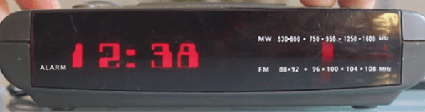
[Sprite] needs an alarm clock to wake up in the morning, and although his phone has an infinitely programmable alarm clock, his ancient Phillips AJ-3040 has never failed him. It’s served him well for 15 years, and there’s no reason to throw it out. Upgrading it was the only way, with OLED displays and Linux systems inside this cheap box of consumer electronics.

After opening up the radio, [Sprite] found two boards. The first was the radio PCB, and the existing board could be slightly modified with a switch to input another audio source. The clock PCB was built around an old chip that used mains frequency as the time base. This was torn out of the enclosure along with the old multiplexed LCD.

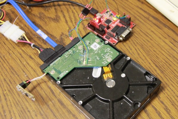
A new display and brain for the clock was needed, and [Sprite] reached into his parts drawer and pulled out an old 288×48 pixel OLED display. When shining though a bit of translucent red plastic, it’s can be a reasonable facsimile of the old LEDs. The brains of the clock would be a Carambola Linux module. After writing a kernel module for the OLED, [Sprite] had a fully functional Linux computer that would fit inside a clock radio.

After having a board fabbed with the power supplies, I2C expanders, USB stereo DAC, and SPI port for the OLED, [Sprite] had a clock radio that booted Linux on an OLED screen. In the video below, [Sprite] walks through the functions of the clock, including setting one of the many alarms, streaming audio from the Internet, and changing the font of the display. There’s also a web UI for the clock that allows alarms to be set remotely – from a phone, even, if [Sprite] is so inclined.

Continue reading “[Sprite_TM] Puts Linux In A Clock Radio”

Sprite Graphics Accelerator On An FPGA

A demo running on a FPGA sprite accelerator

Graphics accelerators move operations to hardware, where they can be executed much faster. This is what allows your Raspberry Pi to display high definition video decently. [Andy]’s latest build is a 2D sprite engine, featuring hardware accelerated graphics on an FPGA.

In the simplest mode, the sprite engine just passes commands through to the LCD. This allows for basic control. The fun part sprite mode, which allows for sprites to be loaded onto the FPGA. At that point, you can show, hide, and move the sprite. By overlapping many sprites, you something like the demo shown above.

The FPGA is from Xilinx, and uses their Block RAM IP to store the state of the sprites. The actual sprite data is contained on a 128 Mb external flash chip, since they require significant space.

The game logic runs on a STM32 Cortex M4 microcontroller which communicates with the FPGA and orders the sprites around. The FPGA then deals with generating frames and sending them to the LCD screen, freeing up the microcontroller.

If you’re wondering about the LCD itself, it’s 3.2″, 640 x 360, and taken from a Ericsson U5 Vivaz cellphone. [Andy] has a detailed writeup on reverse engineering it. After the break, he gives us a video overview of the whole system.

Continue reading “Sprite Graphics Accelerator On An FPGA”

Judge Spotlight: Sprite_TM

Sprite_TM

His friends call him [Jeroen], but everyone else on the Internet knows this god of hacks and mods as [Sprite_TM]. He’s done everything from hacking hard drive controllers to making the best computer ever made even better. As one of the preeminent hardware hackers around, we’re proud to have [Sprite] as a judge in The Hackaday Prize, and happy to interview him on his thoughts on connected devices, the cloud-based Internet of Things, and his process of opening up black box devices for some sometimes subtle modifications.


judge-spotlight-q5You’re well known for your highly technical electronic hacks on your
blog SpritesMods. What about the professional side of your life, what kind
of projects keep you busy there?

judge-spotlight-a5I’m a software developer for a big broadcasting equipment manufacturer. Every now and then a hardware project comes along and I try to grab those too.

Continue reading “Judge Spotlight: Sprite_TM”

[Sprite_TM] OHM2013 Talk: Hacking Hard Drive Controller Chips

Even if he hadn’t done any firmware hacking on this hard drive [Sprite_TM’s] digital exploration of the controller is fascinating. He gave a talk at this year’s Observe, Hack, Make (OHM2013) — a non-commercial community run event in the Netherlands and we can’t wait for the video. But all the information on how he hacked into the three-core controller chip is included in his write up.

[Sprite_TM] mentions that you’re not going to find datasheets for the controllers on these drives. He got his foot in the door after finding a JTAG pinout mentioned on a forum post. The image above shows his JTAG hardware which he’s controlling with OpenOCD. This led him to discover that there are three cores inside the controller, each used for a different purpose. The difference between [Sprite_TM’s] work and that of mere mortals is that he has a knack for drawing surprisingly accurate conclusions from meager clues. To see what we mean check out the memory map for the second core which he posted on page 3 of his article.

Using JTAG he was able to inject a jump into the code (along with a filler word to keep the checksum valid) and run his own code. To begin the firmware hacking portion of the project he pulled the flash ROM off of the board and installed it on that little board sticking out on the left. This made it easy for him to backup and reflash the chip. Eventually this let him pull off the same proof of concept as a firmware-only hack (no JTAG necessary). He goes onto detail how an attacker who has root access could flash hacked firmware which compromises data without any indication to they system admin or user. But we also like his suggestion that you should try this out on your broken hard drives to see if you can reuse the controllers for embedded projects. That idea is a ton a fun!

When we were poking around the OHM2013 website (linked above) we noticed that the tickets are sold out; good for them! But if you were still able to buy them they take Bitcoin as one payment option. Are there any other conferences that allow Bitcoin for registration?

Turning Video Game Sprites Into 3D Objects

Anyone who has played Minecraftfor a good amount of time should have a good grasp on making 3D objects by placing voxels block by block. A giant voxel art dragon behind your base is cool, but what about the math behind your block based artwork? [mikolalysenko] put together a tutorial for making 3D objects out of video game sprites and covers a lot of the math involved in turning pixels into voxels.

The process of modeling a 3D object from a series of 2D images is a very well-studied computer vision problem called multiview stereo reconstruction. This process has been used to build 3D models of random objects with devices such as the Stanford spherical gantry. Unfortunately the math for this algorithm is a mess, but there is another way: using photo hulls (PDF warning) to find the largest possible object from a series of images showing the top, bottom, left, right, front, and back views.

[mikolaly] put together an algorithm to produce 3D images from a series of images and even went so far as to build a web-based shape carving editor. With this web app, it’s possible to make 3D objects simply by inputting a bunch of colored pixels onto six 2D grids.

Once the models were complete, [mikolaly] sent some of the 3D models off to Shapeways for 3D printing. He’s completed Meat boy, Mario, and Link 3D sprites, all available for sale.

Now the only thing left to do is build a script to turn these objects into Minecraft object schematics.

[Sprite_tm] Connects An LCD To A Tiny Linux Board

One of [Sprite_tm]’s colleagues recently challenged him to connect a small LCD touch screen to a Raspberry Pi. Sadly, [Sprite_tm] has yet to take delivery of a Raspberry Pi, but he did manage to connect an LCD to a Linux board without video capabilities.

Because [Sprite_tm]’s display has a 16-bit parallel interface, and 16 GPIO pins are hard to come by on the Carambola Linux board, a few shift registers had to be brought into the build to make the LCD work. These shift registers are connected to the Carambola board via an SPI interface; a very simple way to connect all the LCD pins to the Linux board.

Of course, there’s no way for Linux to speak to the LCD without a kernel driver; [Sprite_tm] wrote a framebuffer driver so the LCD can be used as a console, an X session, or used by any other program that can write to a framebuffer device.

Like all good driver authors, [Sprite_tm] is giving away the patch to enable SPI-ified LCD panels on the Carambola along with the shift register schematic. With any luck we’ll also see the Raspi drivers when [Sprite_tm] takes delivery of his Raspberry Pi.

[Sprite_tm]’s Three-component FM Transmitter

When the Regency TR-1 transistor radio came out onto the market in the 1950s, it was hailed as a modern marvel of microelectronics. With only four transistors and a handful of other components, the TR-1 was a wonder of modern engineering. [Sprite_tm] may have those old-timers beat, though. He built an FM transmitter with the lowest parts count of any transmitter ever.

Like most of [Sprite_tm]’s builds, it’s an unimaginably clever piece of work. [Sprite] overclocked the internal RC oscillator of an ATtiny45 to 24 MHz. After realizing the PLL running at four times the frequency of the oscillator was right in the middle of the FM band, he set about designing a tiny FM transmitter.

[Sprite_tm] remembered his work on MONOTONE and made a short song for hit ATtiny. The firmware for the build takes the notes from his song and varies the 96 MHz PLL frequency a tiny bit, thereby serving as a tiny FM transmitter.

Does it work? Well, if you want to compare it to a Mister Microphone, the range is incredibly limited. That being said it works. It’s an FM transmitter built out of a microcontroller and a battery, and that’s very impressive. Check out [Sprite_tm]’s demo after the break.

Continue reading “[Sprite_tm]’s Three-component FM Transmitter”