Recovering A Busted Video Capture Device With Firmware Flashing Tricks

Sometimes, you have a piece of hardware that just up and stops working on you. In today’s fast-paced world, it’s easy to toss something broken and move on. [BuyItFixIt], as you imagine, makes it their purpose to, well, fix things instead. Their latest efforts involved resurrecting a dead AVerMedia Live Gamer 2 Plus capture device sourced off eBay.

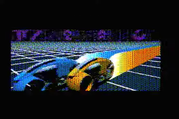
The device was advertised as being dead, with no power. Probing around the board when powered up showed that there was some basic activity going on with one of the flash chips, but the device simply wouldn’t spring to life. This suggested that perhaps the flash had become corrupted, which was confirmed when reading the chip mostly returned 0xFF. Sadly, the device was so badly bricked that the usual update methods via SD card simply wouldn’t work.

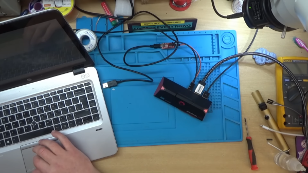
Eventually, hunting down a debug header provided a way in. [BuyItFixIt] was able to find a way to flash firmware over this connection instead, but there was a problem. The firmware they had was formatted for loading via SD card, and wouldn’t work for the debug mode entry route. Instead, getting the device going would require recovering firmware from a similar working device, and then using that as a guide to assemble a proper workable firmware update to get the device back to an operational state.

It’s a great tale of perseverance and triumph, particularly given many would give up after the first update attempt failed. We’ve seen [BuyItFixIt] pull off some heroic repairs before, too. Video after the break.

Continue reading “Recovering A Busted Video Capture Device With Firmware Flashing Tricks”

Video And Audio Playback On Low-End MS-DOS Machines

For most people the phrases ‘MS-DOS’ and ‘video playback’ probably aren’t commonly associated, yet it was quite normal as those of us who were watching full-motion video with games like Command & Conquer can attest to. These audiovisual experiences did however require somewhat more capable hardware than something like an original, 4.77 MHz IBM PC. More recently, however, the removal of these limitations has been turned into a challenge that has been gleefully accepted by hackers, including [Scali] whose recent tinkering with getting not only real-time video but also audio working on these old beasts has been documented on their blog.

Unlike existing early video formats like FLIC from the 1990s, the XDC format developed over the past years enables real-time, 60 FPS video and audio playback on an 8088 IBM PC that has a SoundBlaster 2 and CGA card installed. As [Scali] notes, the SB2 card is convenient, because it enables DMA transports for the audio data, which saves a lot of precious CPU cycles. Unlike the original SB card, it also fixes some teething issues, but an SB2 is hardly ‘low-end’ for an early 1980s PC, so it has to go.

Continue reading “Video And Audio Playback On Low-End MS-DOS Machines”

The Raspberry Pi 5 Can Use External Graphics Cards Now

The Raspberry Pi line is full of capable compact computers, but they’ve never been the strongest in the bunch when it comes to graphical output. Nor have they been particularly expandable in that regard. However, that’s all beginning to change, with [Jeff Geerling] reporting success getting external GPUs to work on the Raspberry Pi 5.

Unlike previous Raspberry Pis, the Raspberry Pi 5 has a less quirky implementation for its PCI Express bus. Previous editions have thrown up issues when trying to work with GPUs, but [Jeff] has found much more success this time around. He’s gotten an AMD RX 460 to work with the setup, and has got it running quite a bit of the glmark2 test regime. He’s working on a variety of other AMD cards too, but suspects NVidia parts could be harder due to some initialization issues that are proving difficult to quash.

It still takes some funky adapters and a lot of work, but finally GPUs are starting to work with the platform. Keep up with his list of card trials on the PiPCI website. We’ve seen [Jeff]’s work with earlier iterations of the Raspberry Pi before, too. Video after the break.

Continue reading “The Raspberry Pi 5 Can Use External Graphics Cards Now”

Make Your Own 1970s Magnetic Stripe Cards

We’re now all used to near-limitless storage on flash and other semiconductor technologies, but there was a time when persistent storage was considerably less easy to achieve. A 1970s programmable calculator from Sharp approached the problem with magnetic strips on special cards, and since [Menadue] has one with no cards, he set about making his own.

These cards are a little different to the credit-card-style cards we might expect, instead they’re a narrow strip with a magnetic stripe down their centre. The unusual feature can be found at the edge, where a row of perforations provide the equivalent of a clock line.

The newly manufactured cards have the clock slots machined along their edges, and then the magnetic part formed from self-adhesive magnetic strip. This last thing is a product we were not aware existed, and can think of plenty of possible applications.

The result as you can see in the video below the break are some cards with variable reliability. There’s a suggestion that white cards might work less well with the infrared light used in the clock detector, also a suspicion the low batteries make reading less easy, but still he’s able to retrieve a stored program. An extinct medium is revived.

Longtime readers will know we’ve spent time in calculator country before.

Continue reading “Make Your Own 1970s Magnetic Stripe Cards”

An 8-bit ISA card with VGA, HDMI and composite video connectors

Upgraded Graphics Gremlin Adds HDMI Video To Vintage PCs

Although new VGA-equipped monitors can still be bought, the old standard is definitely on its way out by now, being replaced by high-speed digital interfaces like HDMI and DisplayPort. It therefore makes sense to prepare for a VGA-less future, as [Yeo Kheng Meng] is doing. He designed an 8-bit ISA display card with an HDMI output that enables even the very first generation of PCs to talk to a modern monitor.

The design is based on the Graphics Gremlin by [Tube Time], which is an 8-bit ISA display card that aims to be software compatible with the obsolete MDA and CGA display formats while outputting a clean VGA signal. [Yeo Kheng Meng] modified the board by adding a TFP410 HDMI bus driver and replacing the rarely-used 9-pin RGBI connector with an HDMI version. He also updated the HDL code for the Lattice FPGA, which forms the heart of the graphics card, to account for the new digital output. While he was at it, he also added a few features he was missing in the original product, such as the option to select the color displayed in MDA mode and the ability to output both HDMI and composite video at the same time.

The video below shows the updated card in action in an IBM 5155 Portable PC. The HDMI port connects to a modern monitor, while the composite video output is routed to the 5155’s internal CRT as well as a small color monitor on top. The IBM thereby joins a small list of retro computers that have received an HDMI upgrade — the Amiga 500 and PlayStation 2 being other examples. HDMI might be a lot more complex to work with than VGA, but luckily there are open-source implementations that do much of the work for you.

Continue reading “Upgraded Graphics Gremlin Adds HDMI Video To Vintage PCs”

The Neo6502 Is A Credit-Card Sized Retro Computer

The venerable MOS Technology 6502 turned up in all kinds of computers and other digital equipment over the years. Typically, it was clocked fairly slow and had limited resources, but that was just how things used to be. Today, the 6502 can run at an altogether quicker pace, and the Neo6502 was the board built to take it there.

The Neo6502 from [Olimex] is a credit-card sized retro computer built around the W65C02. If you’re unfamiliar with that chip, it’s essentially a 6502 that can go fast. How fast? It can be readily overclocked to a blazing 16 MHz, if you’re so inclined!

Unlike some 6502 retro builds, the Neo6502 doesn’t live so firmly in the past. It’s outfitted with an HDMI video interface to make it easy to hook up to modern monitors, so you needn’t fuss around with old displays. Similarly, it has a USB host port to accept input from a keyboard, and audio out via a 3.5 mm jack. There’s also a tiny PCB-mount speaker, as well as I2C, SPI, and UART interfaces. Finally, there’s 2 MB of flash onboard, and a 40-pin connector hosting all the 6502 signals that you know and love. Which is all of them. Much of this lavish equipment comes courtesy of an RP2040 microcontroller onboard that handles all the bits and bobs that aren’t fit for the CPU itself.

It’s still a new project, with things like a BASIC interpreter currently in development and boards not yet openly available.  But, if you’ve always wanted to play with a hotshot 6502, this could be the board for you. Try out the emulator and see how you go.

Continue reading “The Neo6502 Is A Credit-Card Sized Retro Computer”

PCIe For Hackers: Our M.2 Card Is Done

We’ve started designing a PCIe card last week, an adapter from M.2 E-key to E-key, that adds an extra link to the E-key slot it carries – useful for fully utilizing a few rare but fancy E-key cards. By now, the schematic is done, the component placement has been figured out, and we only need to route the differential pairs – should be simple, right? Buckle up.

Getting Diffpairs Done

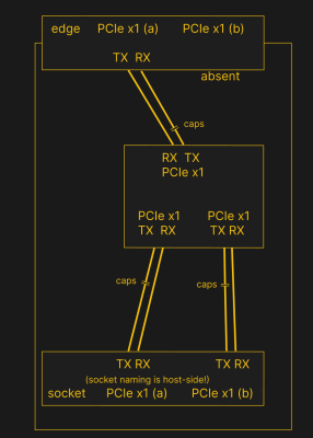
PCIe needs TX pairs connected to RX on another end, like UART – and this is non-negotiable. Connectors will use host-side naming, and vice-versa. As the diagram demonstrates, we connect the socket’s TX to chip’s RX and vice-versa; if we ever get confused, the laptop schematic is there to help us make things clear. To sum up, we only need to flip the names on the link coming to the PCIe switch, since the PCIe switch acts as a device on the card; the two links from the switch go to the E-key socket, and for that socket’s purposes, the PCIe switch acts as a host.

While initially routing this board, I absolutely forgot about one more important thing for PCIe – series capacitors on every data pair, on the host TX side of the link. We need three capacitor pairs here – on TX of the PCIe switch uplink, and two pairs on TX side of the switch – again, naming is host-side. I only remembered this after having finished routing all the diffpairs, and, after a bit of deliberation, I decided that this is my chance to try 0201 capacitors. For that, I took the footprints from [Christoph]‘s wonderful project, called “Effect of moon phase on tombstoning” – with such a name, these footprints have got to be good.

We’ve talked about differential pair calculations before in one of the PCIe articles, and there was a demo video too! That said, let’s repeat the calculations on this one – I’ll show how to get from “PCB fab website information” to “proper width and clearance diffpairs”, with a few fun shortcuts. Our setup is, once again, having signals on outer layers, referenced to the ground layer right below them. I, sadly, don’t yet understand how to calculate differential impedance for signal layers sandwiched between two ground planes, which is to say – if there’s any commenters willing to share this knowledge, I’d appreciate your input tremendously! For now, I don’t see that there’d be a tangible benefit to such an arrangement, anyway.

Continue reading “PCIe For Hackers: Our M.2 Card Is Done”