It might surprise you, Dear Reader, that not every project featured on Hackaday needs to pulsate with LEDs, or update the world about its goings-on over Twitter. They don’t even, contrary to what you may have heard, need to have an Arduino inside. No, sometimes you can pull off a pretty neat hack with nothing more than some wood, a couple of tools, and a unique idea which repurposes something that would otherwise be in a landfill.
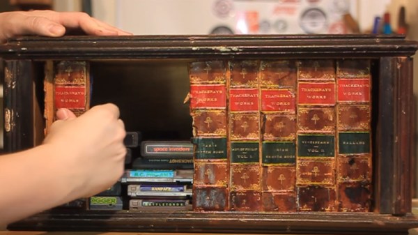
Such is the case with the latest project from [Keith Decent], which uses plywood and the spines of old books to create a secret compartment “bookshelf”. The concept is probably best described as a roll-top desk on its side, and while the action does appear a little stiff, it scores extra points for how easy it looks to replicate.
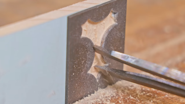
Using a router, [Keith] cuts a channel into the top and bottom sheets of plywood, which the “books” will eventually ride in. This channel goes around the entire perimeter of the shelf, and it’s important to make it as straight as possible so nothing binds up. To make sure things move through as smoothly as possible, some sandpaper is used to clean-up the inside edges.
 The next step is to rip some books apart and salvage their spines. Used books can be purchased for next to nothing at flea markets, so even if you don’t have a home library filled with vintage tomes to eviscerate, it should be easy enough to get your hands on some if you want to build your own version. For sanity’s sake it would seem that books with the same size spines are ideal, so keep an eye out for old sets of encyclopedias and the like.
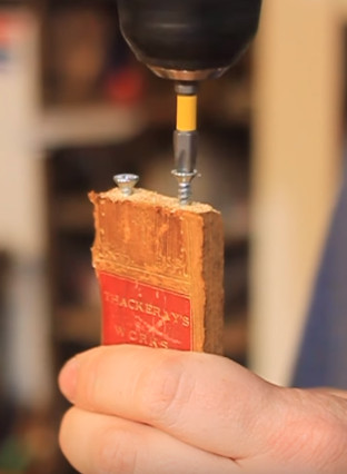
When the spines are removed from the books, they get glued to individual wooden slats. These slats then have holes drilled in the top and bottom, and standard wood screws driven in to act as “rollers”. Real rollers would undoubtedly make for smoother action, but you can’t beat his method if you’re trying to get it done cheaply and quickly.
The slats are then glued onto a piece of fabric, creating what is referred to as a tambour. The fabric backing links all the slats together and makes it so that pushing and pulling one slat will move them all together as one. The book spine tambour is then inserted in the routed channel, and the back panel of the shelf can be installed to lock it all together.
At this point the project is essentially done, but [Keith] does take it the extra mile by sealing all the book spines and doing some finish work on the shelf to make it look more like a real vintage piece of furniture instead of some scrap plywood screwed together.
If this exercise in woodworking has gotten you interested in the wonderful world of dead trees, you’re in luck. We’ve covered several woodworking projects from the hacker perspective, so you won’t be completely lost.
Continue reading “DIY Bookshelf Is More Than Meets The Eye” →

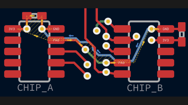
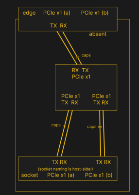 PCIe needs TX pairs connected to RX on another end, like UART – and this is non-negotiable. Connectors will use host-side naming, and vice-versa. As the diagram demonstrates, we connect the socket’s TX to chip’s RX and vice-versa; if we ever get confused, the laptop schematic is there to help us make things clear. To sum up, we only need to flip the names on the link coming to the PCIe switch, since the PCIe switch acts as a device on the card; the two links from the switch go to the E-key socket, and for that socket’s purposes, the PCIe switch acts as a host.