LCD-based QR Clock

Here’s a new take on the QR clock concept that uses an LCD display. The concept comes from the work [ch00f] put into his two versions of a QR clock (both of which used LED arrays). The time of day is encoded using the Quick Response Code standard. This version generates a new code each second which encapsulates date, hour, minute, and second information. If you look at the image on the left you’ll notice the code is not centered. Take a look at the video after the break and you’ll see that’s because it’s bouncing around the LCD like a screensaver. Watch a little longer and you’ll see the psychedelic effects shown in the image on the right.

A PIC32 is driving the display. It’s connected to a DCF77 radio module which feeds the system atomic clock data. The color plasma effects are used to show when the device has locked onto the radio signal.

Continue reading “LCD-based QR Clock”

Making A QR Clock Bigger, Cheaper, And Better

With the massive response and blog cred from his QR Code clock, [ch00f] felt it was time to step up his game and update his design to a proper commercial product. His new QR clock is bigger, brighter, cheaper, and in every way better than the old version, but these improvements came at a cost.

The LED matrices [ch00f] used in his earlier, smaller version weren’t very aesthetically pleasing. He wanted the lights to shine a brilliant white, and also be somewhat attractive when not illuminated. The 8×8 LED arrays [ch00f] picked up from Futurlec had a disgusting yellow coating on each LED that turned light emitted by the blue LEDs inside to a brilliant white. This simply wouldn’t do for a commercial product with [ch00f]’s name on it, so he turned to the one place in the universe where everything was for sale: alibaba.com.

After some trials and tribulations with component manufacturers in China, [ch00f] had the perfect LED matrix; not too expensive, very good quality control, and something that looked really good when both unpowered and illuminated.

Now that his boards are being spun up, [ch00f] hopes to sell his QR clock on Tindie. Each 24×24 LED matrix should cost less than $100, a pretty good deal if you ask us. He’d like to know if anyone out there has any feature requests, to which we can only say he should get rid of the PCB border. Tiling a few of these displays and controlling them via serial would be much cooler than a QR Code clock.

Months Of Failure Lead Up To This EL Panel Dimmer That Pulses To The Music

el-panel-dimmer

Way back in March [Ch00f] took on a for-hire project to make a suit that lights up to the music. He decided to build something based around a pulsating EL panel. He’s put a lot of time and tried of a few different techniques, but he finally has a working EL panel dimmer.

This is a saga we’ve kept our eye on. The fall seems to have been good to him, after a failure using TRIACS he managed to adjust the brightness of some EL wire by messing with the current going to the driver’s oscillator. Standing on the shoulders of that success he designed the board seen above by getting serious about audio signal processing. There’s a microphone on the board which picks up sound which is then processed into a signal responsible for the brightness of the EL panel.

There’s a demo video after the break, but you’ll want to dig into his article to get all the gritty details.

Continue reading “Months Of Failure Lead Up To This EL Panel Dimmer That Pulses To The Music”

POV Wheels For A Longboard

If you don’t mind working with really small components this POV wheel project for a longboard will certainly attract some attention.

The name of the game here is small and cheap. Small because the wheels are only 72mm in diameter (about 2.8 inches). Cheap because [Ch00f] wants to produce and sell them locally. He went with an ATtiny24 microcontroller driving fifteen LEDs. Obviously this will present a problem as the uC uses a 14-pin SOIC package and that’s just not enough I/O to drive the LEDs individually. Add to that the issue of storing patterns to be displayed and you start to run out of program memory very quickly.

But obvious he pulled it off. The image above shows the wheel displaying the CT logo (for ch00ftech.com) and there are several other patterns shown off in the clip after the break. The LEDs are multiplexed, but the wheel spins fast enough that this turns out to be okay. The rotation is measured by an IR reflectance sensor aimed at the stationary axle. A CR2032 powers the device, with some counterweights added to keep the wheel balanced.

Our only concern is the fragility of the exposed electronics. But if you hit the right BOM price we guess you can just replace the board as needed.

Continue reading “POV Wheels For A Longboard”

QR Clock Is Unreadable By Humans And Computers Alike

The clock is a perfect technology. For just a few dollars, you can buy a digital wristwatch and chronometer able to keep extremely accurate time for years without winding a spring or replacing a battery. Anything ‘improvement’ on the design of a clock only makes it harder to read, a feature exploited by the very 1337 binary clocks we see from time to time. [Ch00f] decided it was time to give way to the march of progress and build a completely unreadable clock. He came up with a QR code clock that is unreadable by humans and cellphones alike.

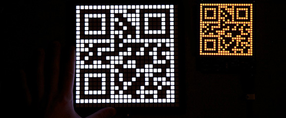
The hardware is built around nine 8×8 LED matrix panels resulting in a 24 x 24 pixel display, perfect for displaying a 21 pixel square QR code. The LED drivers are a standard multiplexed affair, but this project really shines in the firmware department.

The microcontroller [Ch00f] used – an ATMega328 – is far too small to store the 1440 QR codes for every minute of the day. No, this project would have to dynamically generate QR codes on the fly, not exactly an easy problem.

After looking over the official QR code standard, [Ch00f] wrote a rather large program that turns alphanumeric sequences into QR code. This runs on the microcontroller every minute, generating a new QR code for every minute of the day.

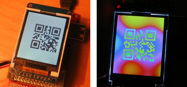
It’s nigh impossible for a human to read a QR code, but [Ch00f] figured he could make his project even less useful. By multiplexing the LEDs at a very low duty cycle [Ch00f] made it impossible for a camera to capture the entire QR code, even though the pattern of pixels is still visible to the human eye. A fabulously useless build that really steps up the game for unreadable clocks.

Video after the break.

Continue reading “QR Clock Is Unreadable By Humans And Computers Alike”

How TO Dim EL Wire: Current Limiting The Oscillator!

[Ch00f] finally made a breakthrough with his efforts dimming EL wire.  He’s been at it for months and the last we heard his TRIAC idea had sputtered out. Not to be discouraged and with an determination we have to admire he has been hard at work reverse engineering others’ and developing his own methods. He put all of this knowledge to task helping a friend of his with a sleeping disorder, and made a dream-catcher that pulses at the approximate rate of an average person’s breathing (as determined by Apple for their pulsing power button lights).

Essentially the whole thing boils down to simply using a transistor to limit the current to the oscillator. A 555 timer is used to pass a triangle wave to the current limiting transistor at approximately the same rate as the Apple button (1/5 Hz). [Ch00f] notes that this isn’t the sinusoidal wave that apple uses, but it’s good enough. Finally a timeout power off is built in to the night light using a decade counter to monitor the number of triangles from the 555. This should keep the EL wire from wearing down faster, though we are hard pressed to  think of a project we used EL on that has lasted anywhere near the 7 year service life of the wire.

Check out [Ch00f]’s page as he walks us through the process, or just watch his circuit in action after the jump!

Continue reading “How TO Dim EL Wire: Current Limiting The Oscillator!”

How Not To Dim EL Panels, TRIACs!

We’ve all been there: an exciting brilliant idea, scratched onto a napkin, hastily plugged into a breadboard, all for naught.  Even the best ideas sometimes suffer from a heavy dose of reality.  [Ch00f] over at ch00ftech recently had a similar experience dimming an EL panel of his using a TRIAC and some clever waveform manipulation. Instead of tossing the parts across the room in a fit aside and moving on he goes into a detailed analysis of what went wrong.

This method differs from the way most EL drivers dim output loads, instead of chopping the output like a PWM controlled LED the TRIAC snips the ends of the waveform and makes an ugly but less powerful output. The issue with this method is that when you cut the waveform during non-zero crossings it causes massive current spikes. These can wreak havoc on a cheap EL inverter and generally cause headaches all around.  [Ch00f ] speculates that his woes may be due to the fact that EL wire is a capacitive load, causing voltage to fall out of phase with the current. This is one of those engineering problems with a thousand and one answers, we can’t wait to see what he comes up with.

Check out the writeup for all the “deets” (as [ch00f] would say) as it is a pretty good primer on TRIAC operation. If there isn’t enough glowy wire in this post you can also check out this sound reactive panel or an informative guide on EL or even more from [ch00f] in general.