Writing On LEDs With A Laser Pointer

After [Ch00f] got his hands on an 8×8 LED display, he didn’t make a 64-pixel video game or VU meter. He made a laser doodler, allowing him to draw on this display with only a laser pointer.

Using LEDs as light sensors is nothing new; [Forrest Mims III] discovered that LEDs can also detect light way back in the late 60s. [Ch00f] played around with this concept before creating a circuit that uses an LED as both a light emitter and sensor that reacts to the ambient brightness.

[Ch00f]’s laser doodler takes this phenomena and applies it to an Adafruit bicolor LED matrix. When a light shines on an individual pixel in the display, the ATMega48 senses the current and turns that pixel on. Since this these pixels have two colors, [Ch00f] used a latch circuit and a button to cycle between what color the ‘Mega writes to the display.

In the video after the break, [Ch00f] shows off his display by having the LEDs light up in response to a laser pointer. It may be a bit small, but we can see a lot of potential for something like this as a gigantic art installation.

Continue reading “Writing On LEDs With A Laser Pointer”

How’s The 60Hz Coming From Your Wall?

If you’ve ever wondered why NTSC video is 30 frames and 60 fields a second, it’s because the earliest televisions didn’t have fancy crystal oscillators. The refresh rate of these TVs was controlled by the frequency of the power coming out of the wall. This is the same reason the PAL video standard exists for countries with 50Hz mains power, and considering how inexpensive this method of controlling circuits was the trend continued and was used in clocks as late as the 1980s. [Ch00f] wondered how accurate this 60Hz AC was, so he designed a little test.

Earlier this summer, [Ch00f] bought a 194 discrete transistor clock kit and did an amazing job tearing apart the circuit figuring out how the clock keeps time. Needing a way to graph the frequency of his mains power, [Ch00f] took a small transformer and an LM311 comparator. to out put a 60Hz signal a microcontroller can read.

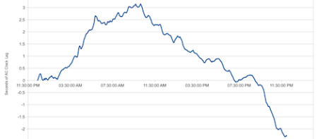
This circuit was attached to a breadboard containing two microcontrollers, one to keep time with a crystal oscillator, the other to send frequency data over a serial connection to a computer. After a day of collecting data, [Ch00f] had an awesome graph (seen above) documenting how fast or slow the mains frequency was over the course of 24 hours.

The results show the 60Hz coming out of your wall isn’t extremely accurate; if you’re using mains power to calibrate a clock it may lose or gain a few seconds every day. This has to do with the load the power companies see explaining why changes in frequency are much more rapid during the day when load is high.

In the end, all these changes in the frequency of your wall power cancel out. The power companies do the same thing [Ch00f] did and make sure mains power is 60Hz over the long-term, allowing mains-controlled clocks to keep accurate time.

Building A Sound Reactive EL Panel And Learning Something In The Process

We’ve seen a lot of builds using electroluminescent wire, usually in the realm of costumes and props. Unfortunately, most electrical engineers don’t deal with blinking and dimming EL wire and panels and any tinkerer trying to control electroluminescence doesn’t have a lot of resources on how to control EL stuff. [ch00f] wanted to fill this knowledge gap, so he build a sound reactive EL panel driver and learned a lot in the process.

Nobody really knows how electroluminescent wire and panels work on a molecular level, but [ch00f] did know that changing the direction of an electric field will cause the EL material to glow. Changing the frequency of this electric field will change the EL material’s brightness, so all [ch00f] had to do was make a variable-frequency EL driver – something that’s a lot harder than it sounds.

We won’t bore you with the details because we  couldn’t do [ch00f]’s write up any justice. We will skip to the end and tell you [ch00f] was able to make a sound reactive EL panel after a month of work that included making his own transformers and doing a whole bunch of math. You can check out the video of [ch00f]’s [Tony Stark]-esque EL panel after the break.

Continue reading “Building A Sound Reactive EL Panel And Learning Something In The Process”

Over Engineering Windshield Wipers To Sync To Music

In the late 90s, Volkswagen aired a series of awesome television advertisements that won a few awards relevant to those in advertising circles. One of these ads was titled Synchronicity and showed a VW Jetta’s windshield wipers (among other things) syncing to music as the car drove down a rainy alley. [ch00f] thought beat tracking wipers would make for a great project, and we love the sheer amount of engineering that went into this build.

The build began with [ch00f] taking apart his wiper motor to get some specifics for his build. Ideally, a rotary encoder would be very useful for this project, but designing a durable encoder would be a pain anyway. [ch00f] had to settle with the ‘parking pins’ on the wiper gear motor that allow the wipers to be driven in intermittent mode.

[ch00f] spent a great deal of time writing code that would guarantee a constant wiper speed, but that didn’t solve the problem of phase, or having the wipers begin or end their cycle on the beat. This problem was somewhat solved (as you can see in the video after the break) by using a feed forward system – basically, the software would predict the change in phase needed and correct it by changing the speed.

The build still isn’t perfect, although that’s mainly due to the placement of wiper parking switch on the wiper motor. [ch00f] plans on spending a little more time correcting the wiper speed/phase control with software, but what he’s got now is still very impressive.

Continue reading “Over Engineering Windshield Wipers To Sync To Music”

Sound Reactive Kanye Glasses!

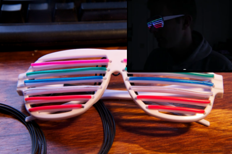
[Ch00f] has decided to ring in the new year with some el wire Kanye glasses. Technically the term for the glasses is either “shutter shades” or “slatted sunglasses”, invented around the 80s by [Alain Mikli] and originally given the nickname “Venetian Sunglasses”. Kanye West evidently got his own retro redesign by the original creator and the rest is history. That is enough Wikipedia for now. [Ch00f] has augmented the original design with six multicolor tracks of EL wire mounted to the shutters of the glasses. The EL wire is fed back through several discrete wires around the wearers ear and to two control boxes. As the video shows, the glasses function as a crude V/U meter based on the audio received by the driver circuit.

Instead of the typical microcontroller [Ch00f] (who has some kind of deep seated issues agaist the Arduino) decided to go full blown analog with the entire design. The audio signal is fed through various Op Amp circuits first amplifying the weak microphone signal then filtering with a low pass filter to focus on the bass frequencies. The filtered bass is then sent to an envelope detector to turn the audio wave into a DC voltage signal. Keeping with the Op Amp design [Ch00f] then uses a resistor ladder and six comparator circuits (with TRIACs on their outputs) to tune the trigger voltage levels of the EL bars. The TRIACs get to deal with the 100 or so volts for the EL strips so that [Ch00f] doesn’t have to party with six EL power supplies in his pocket. For those of you counting at home, that is a total of 13 Op Amps.

The results are fantastic, check the video below to see the glasses in action. Reportedly the circuit does freak out and lock all of the TRIACs in an on state, but a covert flip of the power switch fixes the issue for now. [Ch00f] admits that the project was rather rushed due to the impending new year’s eve party, but now that that is all over with we just need to get [Ch00f] to roll out a stereo version. If you need more [ch00f] we have covered a few of his projects before such as his Icebreaker POV toy hack and a ghetto accelerometer using a reflection sensor.

Thanks for the tips [Daniel] and [Sanchoooo], also via [reddit]. Happy new year!

Continue reading “Sound Reactive Kanye Glasses!”

Reverse Engineering The Icebreaker POV Toy

[Ch00f] spent some serious time figuring out how the Icebreaker POV toy works. This is a pretty cool device about the size of a toothbrush holder. It’s in a clear plastic case, which lets the row of 32 surface mount LEDs shine through. But making light isn’t their only function. You can use the device to scan in a high-contrast design, then ‘play it back’ using the persistence of vision display properties of the LED strip.

Perhaps the biggest question on [Ch00f’s] mind was how the sensing is done. He made a series of observations, then started monkeying around with the LEDs to investigate them. It seems that one LED is lit up while the ones around it are used as light sensors. This becomes more confusing once he realized that the display was multiplexed.

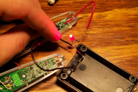
His write-up includes a collection of schematics that can be pieced together to conceptualize the entire circuit. The image above was taken during this process, using an LED to check the connections on a part. This let him prove that it’s an N-channel MOSFET. He plans to take what learned and roll it into his own project.

[via Reddit]

POV Bauble Uses DIY Accelerometer To Sync The Image

So we saw this tip come in and thought–oh, another POV device. We watched the video (embedded after the break), took a sip of coffee, then almost sprayed the beverage all over the computer when we realized that this uses a diy sensor to synchronize the POV image.

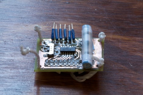
[Ch00f] came up with the idea for the sensor after seeing a similar implementation on a commercial POV toy. Instead of using a proper accelerometer to sense the motion, the toy uses a plastic bead in a channel. When you move the body of the toy the bead rolls to one end or the other, covering or exposing a reflective sensor.

A similar sensor is used here. A drinking straw servers as the channel, with a paper-covered nylon screw as the bead. [Ch00f] cut a window in the bottom of the straw for his reflective sensor, then sealed each end with a wad of paper.

This method works, but not as well as he had hoped. It seems the refresh rate and timing of the particular sensor he’s using is rather poor. If it were replaced with one that is simply and IR LED and phototransistor (like the sensors from [Jack’s] last video) he thinks it would work a lot better.

via Buildlounge.

Continue reading “POV Bauble Uses DIY Accelerometer To Sync The Image”