Remote Tester

A Simple Circuit For Testing Infrared Remote Controls

Every now and then a remote control acts up. Maybe you are trying to change the channel on your television and it’s just not working. A quick way to determine if the remote control is still working is by using a cell phone camera to try to see if the IR LED is still lighting up. That can work sometimes but not always. [Rui] had this problem and he decided to build his own circuit to make it easier to tell if a remote control was having problems.

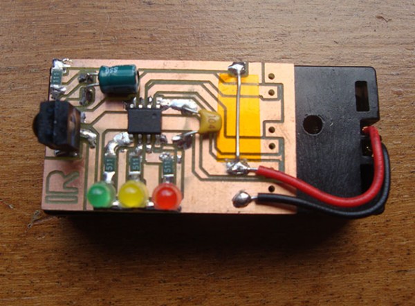
The circuit uses a Vishay V34836 infrared receiver to pick up the invisible signals that are sent from a remote control. A Microchip 12F683 processes the data and has two main output modes. If the remote control is receiving data continuously, then a green LED lights up to indicate that the remote is functioning properly. If some data is received but not in a continuous stream, then a yellow LED lights up instead. This indicates that the batteries on the remote need to be replaced.

The circuit also includes a red LED as a power indicator as well as RS232 output of the actual received data. The PCB was cut using a milling machine. It’s glued to the top of a dual AAA battery holder, which provides plenty of current to run the circuit.

Infrared-controlled Light Switch

If you’re looking for your first electronics project, or a project to get someone else started in electronics, [Vadim] has you covered. Back when he was first starting out in electronics he built this infrared-controlled light switch that works with a standard TV remote control.

[Vadim]’s first few projects ended up as parts for other projects after they were built, so he wanted to build something useful that wouldn’t ultimately end up back in the parts drawer. The other requirements for the project were to use a microcontroller and to keep it simple. [Vadim] chose an ATtiny2313 to handle the RC-5 IR protocol and switch the light.

The circuit still has a switch to manually control the lights, preserving the original functionality of the light switch. The rest of the design includes a header for programming the board and another header for tying into the high voltage lines. This is a great project for anyone who knows what they’re doing with mains power but is just getting started with microcontrollers. If properly designed and implemented you’ll never stumble across a room to turn the lights out again!

Perhaps mixing high and low voltages on the same circuit board doesn’t spark your fancy or you can’t modify the light switch in your place of residence? Check out this mechanically-switched light switch.


Infrared Controlled Remote Firework Igniter

Firework Igniter

With Independence Day just around the corner, American hackers are likely to find themselves blowing things up in the name of Independence. It’s all great fun but it can also be dangerous. The standard ignition method of “use a lighter and run away really fast” is not exactly safe. Instead of lighting your fireworks the old-fashioned way, why not follow [Facelesstech’s] example and build your own infrared controlled remote igniter?

The first step was to decide how to actually ignite the firework fuse. [Facelesstech] had seen others use a car cigarette lighter for this purpose and he decided to follow in their footsteps. He started by removing the cigarette lighter from his own car and pulling it apart. Only one component was needed for this hack. The main heating element is a small disk with a “stem” on the end. If you apply 12V to the stem and attach the outer edge of the disk to ground, the igniter will quickly become hot.

[Facelesstech] originally thought he could just solder some wires to the device. However, the heating element gets so hot that the solder just melts every time it’s turned on. He then got creative and drilled a hole in a small block of wood that fits the heating element. The element is bolted into the wood and the bolt is used as a conductor for the electrical power.

The heating element is powered via a 12V relay. The relay is controlled by an Arduino Nano. The Nano allows two modes of operation. With the first mode, you simply press a button and the Nano will start a five second timer. The idea is to give you enough time to run to a safe distance before the firework is ignited. This isn’t much different from the old-fashioned method, but it does give you a slightly extended fuse. The second mode is where the project really shines. The Nano is also hooked up to an infrared receiver. This allows [Facelesstech] to press a button on an old television infrared remote control to active the igniter. This is a clever solution because it allows you to get to a safe distance without having to run a long wire. It’s also simple and inexpensive. Be sure to watch the video test of the system below. Continue reading “Infrared Controlled Remote Firework Igniter”

A Light Painting Infrared Ray Gun

gun

[Noe] over at Adafruit has a really great build that combines the Internet’s love of blinkey LEDs and rayguns with the awesome technology behind extraordinarily expensive thermal imaging cameras. It’s a light painting infrared heat gun, used for taking long exposure photographs and ‘painting’ a scene red or blue, depending on the temperature of an object.

While this isn’t a proper FLIR camera, with a DSLR and a wide open shutter, it is possible to take pseudo-thermal images by simply ‘painting’ a scene with the light gun. This is an absurdly clever technique we’ve seen before and has the potential to be a useful tool if you’re looking for leaks around your windows, or just want to have a useful cosplay prop.

The circuit inside this raygun is based on a contactless infrared sensor connected to an Adafruit Gemma, with the LEDs provided by a NeoPixel ring. There are two 3D printable cases – your traditional raygun/blaster, and a more pragmatic wand enclosure. With either enclosure, it’s possible to take some pretty heat map pictures, as seen in the video below.

Continue reading “A Light Painting Infrared Ray Gun”

Modular Arduino Based Infrared Thermometer

IRTemperature

[Brian] started out with a clear and concise goal, “allow a regular human to associate an audible tone with a temperature from an infrared contactless thermometer.” With his latest project, the ESPeri.IRBud, he has achieved this goal.

One of our favorite parts of [Brian’s] post is his BOM. Being able to easily see that the IR temperature sensor costs $26 at DigiKey is unbelievably helpful to readers. This specific sensor was chosen because others have successfully interfaced it with the Arduino. Not having to reinvent the wheel is good thing! For the build, [Brian] decided to hook up the IR temperature sensor to a re-purposed flexible iPhone headset wire. Having used headphone sockets to connect to the sensor and speakers, the actual device is quite modular. Hearing this thing in action is quite cool, it almost sounds like old-school GameBoy music! Check it out after the break.

Have you used an IR temperature sensor in one of your projects? Let us know.

Continue reading “Modular Arduino Based Infrared Thermometer”

3D Scanner Using A Sharp Infrared Sensor

[Fernando] sent in a tip about a pet project he’s been working on. It’s an interesting take on a 3D scanner. He used a stepper motor to rotate the object being scanned, and an Arduino for control, but the real novelty is the way he used the sensor. [Fernando] mounted a Sharp GP2D120X on vertical surface, and used a second stepper motor to raise the sensor during the scan. As you can see in the videos (embedded after the break), this results in the scan being put together in an ascending spiral.

The Sharp sensor is cheap and decent, but you’re obviously not going to get amazing accuracy. Still, using the average of several measurements, he ends up with a decent result. Happily, [Fernando] has released the code, and it should be easy enough to repurpose it with a more accurate sensor. It would be interesting to see a laser-based sensor paired with this code.

Continue reading “3D Scanner Using A Sharp Infrared Sensor”

Cloning An Infrared Disarming Remote Of A $8 Home Security System

5

[Sylvio] decided to buy one of the cheap alarm systems you can find on the internet to have a look at its insides. The kit he bought was composed of one main motion sensor and two remote controls to arm/disarm it.

Communication between the remotes and the sensor is done by using infrared, requiring a direct line of sight for a signal to be received. Modern alarm systems typically use RF remotes with a typical frequency of 434MHz or 868MHz.  In his write-up, [Sylvio] first tries to replicate the IR signal with one of his ‘learning remote controls’ without success and then proceed to reverse engineering the remote circuit shown in the above picture. Hackaday readers may figure out just by looking at it that it is a simple astable multivibrator (read ‘oscillator’). Its main frequency is 38.5kHz, which is typical for IR applications. Therefore, if one of your neighbours had this ‘security system’ one could just disarm it with any of the same remotes…

[Sylvio] then explains different ways to replicate the simple IR signal, first with an Arduino then with a frequency generator and finally using the USB Infrared Toy from Dangerous Prototypes. We agree with his conclusion: “you get what you pay for”.