800 X 600 VGA With The STM32F4

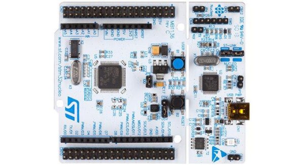
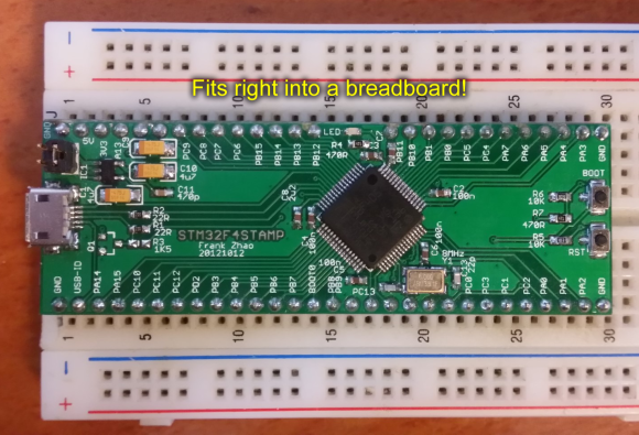
Generating VGA is a perennial favorite on the Hackaday tips line, and it’s not hard to see why. Low-res video games, of course, but sending all those pixels out to a screen is actually a pretty challenging feat of coding. The best most project have attained is the original VGA standard, 640×480. Now that we have fast ARMs sitting around, we can bump that up to 800×600, like [Karl] did with an STM32F4 Discovery board.

The problem with generating VGA on a microcontroller is the pixel frequency – the speed at which pixels are shoved out of the microcontroller and onto the screen. For an 800×600 display, that’s 36 MHz; faster than what the 8-bit micros can do, but a piece of cake for the STM32F4 [Karl] is using.

[Karl] started his build by looking at the VGA project Artekit put together. It too uses an STM32, but a 36-pin F103 part. Still, it was fast enough to generate a line-doubled 800×600 display. [Karl] took this code and ported it over to the F4 part on the Discovery board that has enough space for a full 800×600 frame buffer.

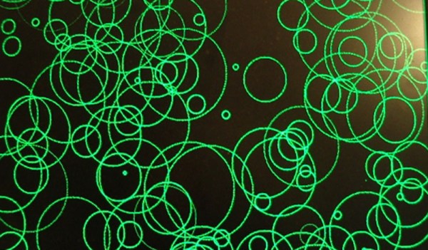
With all that RAM on board the F4 part, [Karl] was able to expand the frame buffer and create a relatively high-resolution display with DMA and about a dozen lines of code. It looks great, and now we just need a proper application for high-resolution VGA displays. Retrocomputing? A high-resolution terminal emulator? Who knows, but it’s a great use for the STM32.

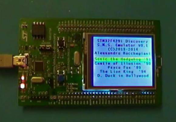
If circles and some text aren’t your thing, Artekit also has Space Invaders running on the 36-pin STM32.

Game Boy Cartridge Emulator Uses STM32

Game Boys may be old tech, but they still provide challenges to modern hackers. [Dhole] has come up with a cartridge emulator which uses an STMicroelectronics STM32F4 discovery board to do all the work. Until now, most flash cartridges used programmable logic devices, either CPLDs or FPGAs to handle the high-speed logic requirements. [Alex] proved that a microcontroller could emulate a cartridge by using an Arduino to display the “Nintendo” Game Boy boot logo. The Arduino wasn’t fast enough to actually handle high-speed accesses required for game play.

[Dhole] kicked the speed up by moving to the ARM Cortex-M4 based 168 MHz STM32F4. The F4’s  70 GPIO pins can run via internal peripherals at up to 100MHz, which is plenty to handle the 1MHz clock speed of the Game Boy’s bus. Logic levels are an issue, as the STM32 uses 3.3V logic while the Game Boy is a 5V device. Thankfully the STM32’s inputs are 5V tolerant, so things worked just fine.

Simple Game Boy cartridges like Tetris were able to directly map a ROM device into the Game Boys memory space. More complex titles used Memory Block Controller (MBC) chips to map sections of ROM and perform other duties. There were several MBC chips used for various titles, but [Dhole] can emulate MBC1, which is compatible with the largest code base.

One of the coolest tricks [Dhole] implemented was displaying a custom boot logo. The Game Boy used the “Nintendo” logo as a method of copyright protection. If a cartridge didn’t have the logo, the Game Boy wouldn’t run. The logo is actually read twice – once to check the copyright info, and once to display it on the screen. By telling the emulator to change the data available at those addresses after the first read, any graphic can be displayed.

If you’re wondering what a cartridge emulator would be useful for (other than pirating games), you should check out [Jeff Frohwein’s] Gameboy Dev page! [Jeff] has been involved in Game Boy development since the early days. There are literally decades of demos and homebrew games out there for the Game Boy and various derivatives. .

Continue reading “Game Boy Cartridge Emulator Uses STM32”

STM32 Nucleo, The Mbed-Enabled, Arduino-Compatable Board

The STM32 line of microcontrollers – usually seen in the form of an ST Discovery dev board – are amazingly powerful and very popular micros seen in projects with some very hefty processing and memory requirements. Now, ST has released a great way to try out the STM32 line with the Nucleo board.

There are two really great features about these new Nucleo boards. First, they’re mbed compatable, making them a great way to get started in the ARM development world. Secondly, they have Arduino pin headers right on the board, giving you access to all your shields right out of the box.

Right now, there are four varieties of the Nucleo board based on the STM32F030, -F103, -F152, and -F401 microcontrollers. The STM32F401 is the high-powered variant, An ARM Cortex-M4 microcontroller running at 84 MHz, 512kB of Flash, and enough I/O for just about any project.

If you’d like to get your hands on one of the STM32 Nucleo boards, you can order a voucher to pick one up at Embedded World in Germany next week. Otherwise, you’re stuck ordering from Mouser or Farnell. Bonus: the high-end F401-based board is only $10 USD.

Sega Master System On A STM32 Development Board

Sega on STM32

Some hackers have managed to convert an STM32 development into a Sega Master System emulator. This means Sonic the Hedgehog running on an ARM Cortex-M4.

This hack has a number of parts. First, [Alessandro Rocchegiani] showed off a video of his Sega Master System emulator running on the STM32F429 Discovery development board. This first version used the on board 2.4″ TFT LCD screen.

[Fabrice] was working with this STM32 Discovery board already. He had developed an expansion board that added a number of features to the development kit, including an R-2R DAC for video output. When [Fabrice] found out about the Sega Master System emulator, he worked with [Alessandro] and his son [Fabrizio] to get VGA output working. They also added support for the Wii controller using [Fabrice]’s Wii library. The result is a Sega Master System emulator with VGA output at 640 x 480, with 16 bit color and Wii controller support.

You can watch a video of both the LCD and VGA versions of the hack after the break.

Continue reading “Sega Master System On A STM32 Development Board”

Building An Engine Control Unit With The STM32F4

If you’re looking to soup up your whip, the first place you’ll probably look is the engine control unit. This computer shoved in the engine compartment controls just about every aspect of your car’s performance, from the air/fuel ratio, the ignition timing, and the valve controls. Upgrading the ECU usually means flashing new firmware on the device, but [Andrey] is taking it one step further: he’s building his own ECU using the STM32F4 Discovery dev board.

[Andrey]’s ride is a 1996 Ford Aspire, but while he was developing his open source ECU, he wanted to be able to drive his car. No problem, as going down to the junkyard, picking up a spare, and reverse engineering that was a cheap and easy way to do some development. After powering this spare ECU with an ATX supply, [Andrey] was able to figure out a circuit to get sensor input to his microcontroller and having his dev board control the fuel injector.

With a few additional bits of hardware [Andrey] has his open ECU controlling the fuel injection, ignition, fuel pump, and idle air valve solenoid. Not a bad replacement for something that took Ford engineers thousands of man hours to create.

[Andrey]’s ECU actually works, too. In the video below, you can see him driving around a snow-covered waste with his DIY ECU controlling all aspects of the engine. If the engine sounds a little rough, it’s because a wire came loose and he was only using two cylinders. A bit of hot glue will fix that, though.

Continue reading “Building An Engine Control Unit With The STM32F4”

Breadboard Friendly ARM Board Based On STM32F4

breadboard-friendly-stm32-dev-board

Umm yeah… this is more like it. The STM32F4Stamp is a project which [Frank Zhao] put together to make his ARM prototyping process more like is was back when everything came in a DIP format. As you can see, it’s just narrow enough to leave one row open on the breadboard for jumper wires.

Don’t get us wrong, we do really like STM’s own Discovery Boards for the hardware they deliver at a very low price. But the dual-row pin headers on the larger versions (all except the F0 variant) make it tricky to connect your peripherals. This is pushed to the point that a large percentage of hacks we’ve seen with the Discovery boards are actually just to make connecting external hardware easier.

You may be thinking that there’s a lot missing from this board, but we disagree. Obviously there’s still a USB port which can be used to power the board via a 3.3V regulator. But since the STM32 chips have a built-in bootloader the USB connection can also be used to flash firmware to the processor. Nice! It’s open hardware if you want roll your own. For your convenience we’ve embedded the schematic after the break, along with [Frank’s] demo video.

Continue reading “Breadboard Friendly ARM Board Based On STM32F4”

Impressive Dev Boards For Your STM32 Dev Boards

stm32-discovery-breakout-boards

It seems there are a lot of people who have the same complaint about the STM32 Discovery boards; it can be difficult to add external hardware to them. Don’t get us wrong, we appreciate all of the pins being broken out (as opposed to the Stellaris Launchpad which we think has too few available). Here’s [Scot Kornak’s] solution to the problem. He created three different baseboards which the STM32 Discovery plugs into. Each is for a different model of dev board: the VL, F3, and F4. But he also thinks the baseboard we saw in this other project is a good choice for an F4 solution.

These large PCB add-ons bring functionality in two different ways. The first is by using expandable ports for drop in modules like serial communications connectors or Analog/SPI/I2C modules. For us, the second method is the most desirable. He routes each GPIO port to a 2×8 header and uses IDC cables (rainbow cable in these images) to connect them to a breadboard. Seeing this makes us wish STM had used discreet clusters of 16 pins instead of those super long dual pin headers.