We appear to be edging ever closer to a solid statement of “We are not alone” in the universe with this week’s announcement of the detection of biosignatures in the atmosphere of exoplanet K2-18b. The planet, which is 124 light-years away, has been the focus of much attention since it was discovered in 2015 using the Kepler space telescope because it lies in the habitable zone around its red-dwarf star. Initial observations with Hubble indicated the presence of water vapor, and follow-up investigations using the James Webb Space Telescope detected all sorts of goodies in the atmosphere, including carbon dioxide and methane. But more recently, JWST saw signs of dimethyl sulfide (DMS) and dimethyl disulfide (DMDS), organic molecules which, on Earth, are strongly associated with biological processes in marine bacteria and phytoplankton.
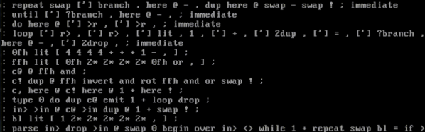
Forth is popular on small computers because it is simple to implement, yet quite powerful. But what happens when you really need to shrink it? Well, if your target is the 6502, there’s milliForth-6502.
This is a port of milliForth, which is a fork of sectorforth. The sectorforth project set the standard, implementing a Forth so small it could fit in a 512-byte boot sector. The milliForth project took sectorforth and made it even smaller, weighing in at only 336 bytes. However, both milliForth and sectorforth are for the x86 architecture. With milliForth-6502, [Alvaro G. S. Barcellos] wanted to see how small he could make a 6502 implementation.
Despite the best efforts of the RepRap community over the last twenty years, self-replicating 3D printers have remained a stubbornly elusive goal, largely due to the difficulty of printing electronics. [Brian Minnick]’s fully-printed 3D printer could eventually change that, and he’s already solved an impressive number of technical challenges in the process.
[Brian]’s first step was to make a 3D-printable motor. Instead of the more conventional stepper motors, he designed a fully 3D-printed 3-pole brushed motor. The motor coils are made from solder paste, which the printer applies using a custom syringe-based extruder. The paste is then sintered at a moderate temperature, resulting in traces with a resistivity as low as 0.001 Ω mm, low enough to make effective magnetic coils.
Entry-level oscilloscopes are a great way to get some low-cost instrumentation on a test bench, whether it’s for a garage lab or a schoolroom. But the cheapest ones are often cheap for a reason, and even though they work well for the price they won’t stand up to more advanced equipment. But missing features don’t have to stay missing forever, as it’s possible to augment them to get some of these features. [Tommy’s] project shows you one way to make a silk purse from a sow’s ear, at least as it relates to oscilloscopes.
Most of the problem with these lower-cost tools is their low precision due to fewer bits of analog-digital conversion. They also tend to be quite noisy, further lowering the quality of the oscilloscope. [Tommy] is focusing his efforts on the DSO138-mini, an oscilloscope with a bandwidth of 100 kHz and an effective resolution of 10 bits. The first step is to add an anti-aliasing filter to the input, which is essentially a low-pass filter that removes high frequency components of the signal, which could cause a problem due to the lower resolution of the device. After that, digital post-processing is done on the output, which removes noise caused by the system’s power supply, among other things, and essentially acts as a second low-pass filter.
In this series of 23 YouTube videos [Rich] puts the AMD Zynq-7000 SoC through its paces by building a development board from the ground up to host it along with its peripherals. The Zynq is part FPGA and part CPU, and while it has been around for a while, we don’t see nearly as many projects about it as we’d like.
[Rich] covers everything from the power system to HDMI, USB, DDR RAM, and everything in between. By the end, he’s able to boot PetaLinux.
S4 slicer uses the path from any point (here, Benchy’s prow) as its basis…
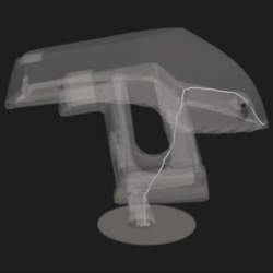
This non-planar slicer is built into a Jupyter notebook, which follows a relatively simple algorithm to automatically generate non-planar toolpaths for any model. It does this by first generating a tetrahedral mesh of the model and then calculating the shortest possible path through the model from any given tetrahedron to the print bed. Even with non-planar printing, you need to print from the print-bed up (or out).
Quite a lot of math is done to use these paths to calculate a deformation mesh, and we’ll leave that to [Joshua] to explain in his video below. After applying the deformation, he slices the resulting mesh in Cura, before the G-code goes back to Jupyter to be re-transformed, restoring the shape of the original mesh.
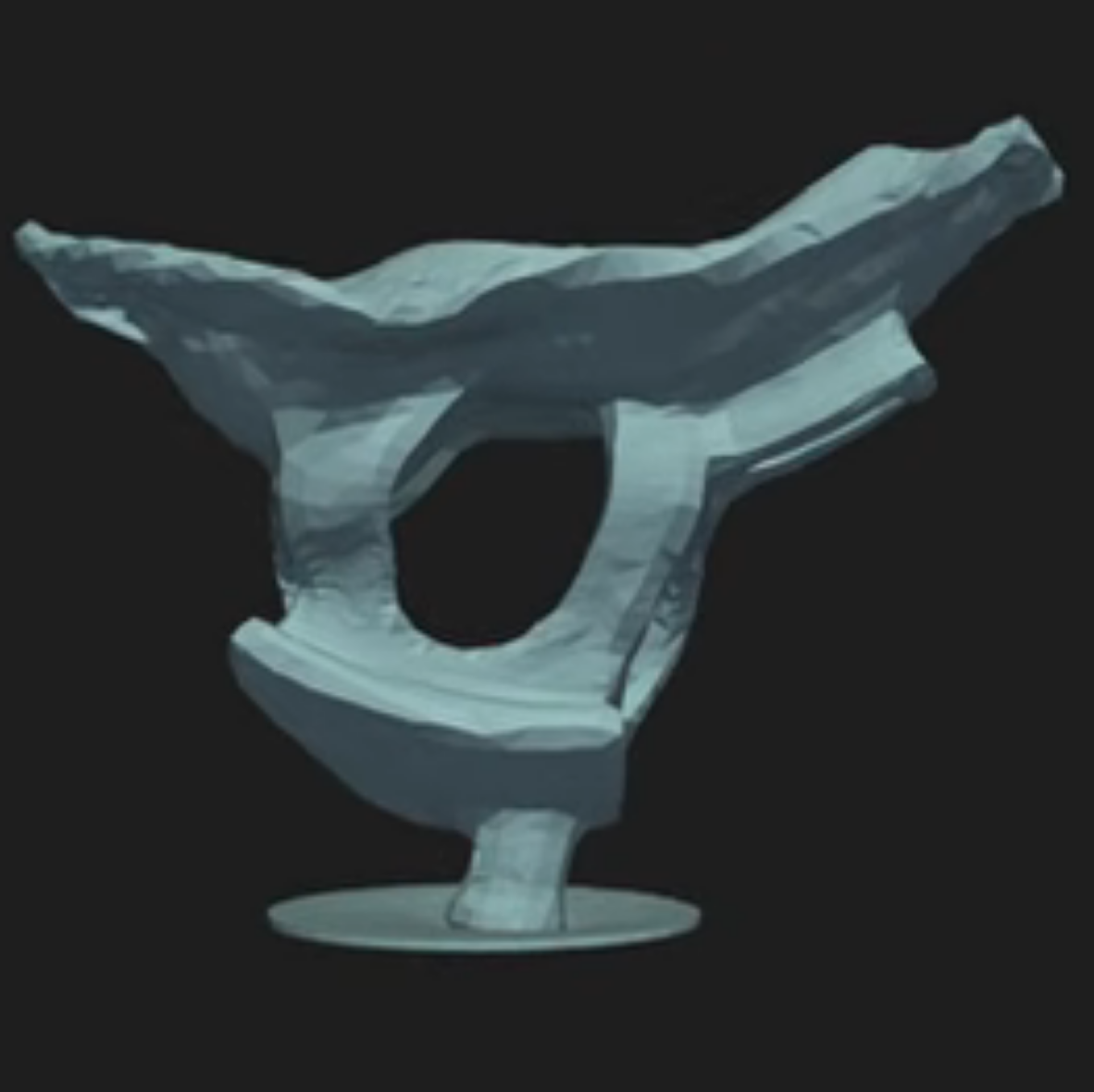
… to generate deformed models for slicing, like this.
So yes, it is G-code bending as others have demonstrated before, but in a reproducible, streamlined, and straightforward workflow. Indeed, [Josh] credits much of the work to earlier work on the S^3-Slicer, which inspired much of the logic and the name behind his S4 slicer. (Not S4 as in “more than S^3” but S4 as a contraction of “Simplified S^3”). Once again, open source allows for incremental innovation.
It is admittedly a computationally intensive process, and [Joshua] uses a simplified model of Benchy for this demo. This seems exactly the sort of thing we’d like to burn compute power on, though.
It’s traditional to launch new software on April Fool’s Day, which is when we heard that Rockbox 4.0 has been released. But, in this case, the venerable MP3 firmware actually did update after a long absence. It’s great to see that good old Rockbox is still kicking along. We first mentioned Rockbox here at Hackaday approaching 20 years ago. How time flies. There used to be a whole ‘scene’ around hacking Personal Media Players (PMPs), also known as “MP3 Players”.
We tracked down Rockbox contributor [Solomon Peachy] to ask for some simple advice: If someone wants to install Rockbox on a personal media player today, what hardware should they buy? [Solomon] referred us to the AIGO EROS Q / EROS K, which is the only compatible hardware still being manufactured and sold. Beyond that, if you want to buy compatible hardware, you’ll need to find some secondhand somewhere, such as eBay. See the Rockbox Wiki for supported hardware.
Smartphones and streaming services have subsumed the single-purpose personal media player. Will you put the new Rockbox on something? Let us know in the comments.


![Benchy, printed upside down on [Josh's] Core R-Theta printer.](https://hackaday.com/wp-content/uploads/2025/04/upside-down-benchy-nonplaner-e1745086286623.jpg?w=600&h=450)